DC microresistivity measuring system

A measurement system and micro-resistance technology, applied in the direction of measuring devices, measuring electrical variables, measuring resistance/reactance/impedance, etc., can solve the problems of amplifier range and temperature drift affecting measurement accuracy, etc., and achieve easy access to devices, mature circuits, and improved The effect of resolution

Active Publication Date: 2012-12-26
HARBIN INST OF TECH
View PDF3 Cites 26 Cited by
  • Summary
  • Abstract
  • Description
  • Claims
  • Application Information

AI Technical Summary

Problems solved by technology

[0007] In order to solve the problem that the measuring range and temperature drift of the amplifier affect the measurement accuracy existing

Method used


Image

  • DC microresistivity measuring system
  • DC microresistivity measuring system
  • DC microresistivity measuring system

Examples


specific Embodiment approach 1

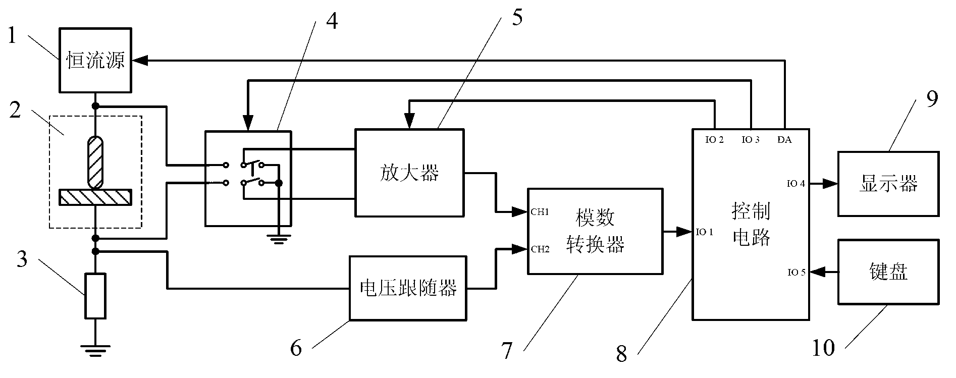
[0023] Embodiment 1: The DC micro-resistance measurement system described in this embodiment includes a constant current source 1, a standard current-sensing resistor 3, an amplifier 5, a voltage follower 6, an analog-to-digital converter 7 and a control circuit 8, and the constant current source 1 is used to provide excitation current to the component under test 2 and the standard current-sensing resistor 3 connected in series; the voltage signal of the standard current-sensing resistor 3 to ground is collected by the voltage follower 6 and then output to the analog-to-digital converter 7. The converter 7 outputs to the control circuit 8 after conversion; the voltage at both ends of the component under test 2 is collected and amplified by the amplifier and then output to the analog-to-digital converter 7, and then output to the control circuit 8 after being converted by the analog-to-digital converter 7;

[0024] A software module is embedded in the control circuit 8, and the ...

specific Embodiment approach 2

[0031] Embodiment 2: This embodiment is a further limitation of the DC micro-resistance measurement system described in Embodiment 1. In this embodiment, the standard current-sensing resistor 3 is realized by a precision high-power wire-wound resistor.

[0032] Precision high-power wire-wound resistors have the advantage of stable resistance. Using this kind of resistor as a standard resistor to realize current detection can improve the measurement accuracy of current, and then improve the measurement accuracy of resistance value.

specific Embodiment approach 3

[0033] Embodiment 3: This embodiment is a further limitation of the DC micro-resistance measurement system described in Embodiment 1 or Embodiment 2. In this embodiment, the amplifier 5 is realized by a differential input amplifier.

[0034] The amplifier in this embodiment adopts a differential input amplifier, which has the advantage of high measurement accuracy and can improve the accuracy of the voltage difference between the two ends of the measured component 4 , thereby ensuring the accuracy of the obtained resistance value of the measured component 4 .


PUM


Abstract

The invention discloses a DC microresistivity measuring system, relating to a DC microresistivity measuring system, belonging to the technical field of measurement and solving the problem that the measuring precision is influenced by measuring range and temperature drift errors of an amplifier in the traditional DC, AC and pulse methods for measuring contact resistance. According to the DC microresistivity measuring system, a constant current source provides excitation current for serially-connected contact pairs to be measured and a standard current sensing resistor; the standard current sensing resistor is used for acquiring a voltage signal to the ground through a voltage follower; and a terminal voltage measuring module for measuring the terminal voltage of the contact pairs to be measured, a current measuring module for acquiring a current value according to the voltage of the standard current sensing resistor and a resistance calculating module for calculating the contact resistance of the measured contact pairs are embedded into a control circuit. The DC microresistivity measuring system has the advantages of realizing measurement of resistance by a mode of combining software and hardware and effectively avoiding the influence of the measuring range, namely the temperature drift, of the amplifier on the measuring precision and can be widely applied to the technical field of measurement of microresistivity.

Description

technical field [0001] The invention relates to a DC micro-resistance measuring system, belonging to the technical field of measurement. Background technique [0002] Contact resistance exists everywhere in the field of electrical technology, and the resistance value of contact resistance is generally relatively small. The measurement of contact resistance belongs to the micro-resistance measurement technology. [0003] The basic principle of this type of measurement technology is voltammetry, which can be subdivided into direct current method, alternating current method and pulse method, etc. [0004] In the direct current method, a known constant current is used to excite the tested part, and the measured resistance value is calculated by amplifying and measuring the contact pair voltage. Due to the large dynamic range of the measured contact voltage, which can generally vary from nV level to V level, the operational amplifier must be able to perform accurate magnificatio...

Claims


Application Information

Patent Timeline
IPC IPC(8): G01R27/14
Inventor 任万滨薛升俊吕辛陈宇郑艳明
Owner HARBIN INST OF TECH
Why Eureka
Try Eureka