
Poly lithium battery structure with high capacity and high output ratio power

A technology with high output and specific power, applied in the direction of secondary batteries, structural parts, battery pack parts, etc., can solve the problems of battery cycle performance deterioration, current density asymmetry, internal resistance increase, etc., to improve the polarization effect Accumulation of thermal effects, reduction of battery polarization effects, and improvement of thermal runaway platforms

Active Publication Date: 2012-12-26
厦门太和动力电源科技有限公司
View PDF10 Cites 8 Cited by
  • Summary
  • Abstract
  • Description
  • Claims
  • Application Information

AI Technical Summary

Problems solved by technology

[0007] Due to the large number of tabs when the tabs are pressed together as a whole, the bending range of the outer tabs is large, resulting in the limitation of the conduction area of ​​the tab metal sheet and the asymmetry of the current density with high output specific power and high current discharge. When discharging under this condition, the internal resistance increases, the temperature rises sharply, and the polarization phenomenon is serious, which will inevitably lead to a sharp deterioration of the battery cycle performance.

Method used

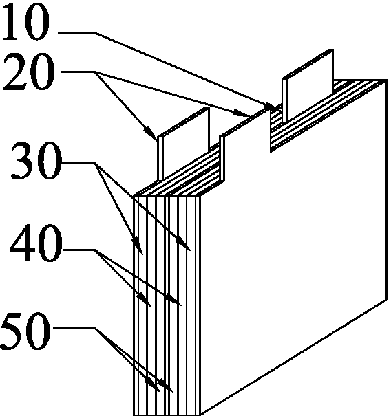

Image

  • Poly lithium battery structure with high capacity and high output ratio power
  • Poly lithium battery structure with high capacity and high output ratio power
  • Poly lithium battery structure with high capacity and high output ratio power

Examples


Embodiment Construction

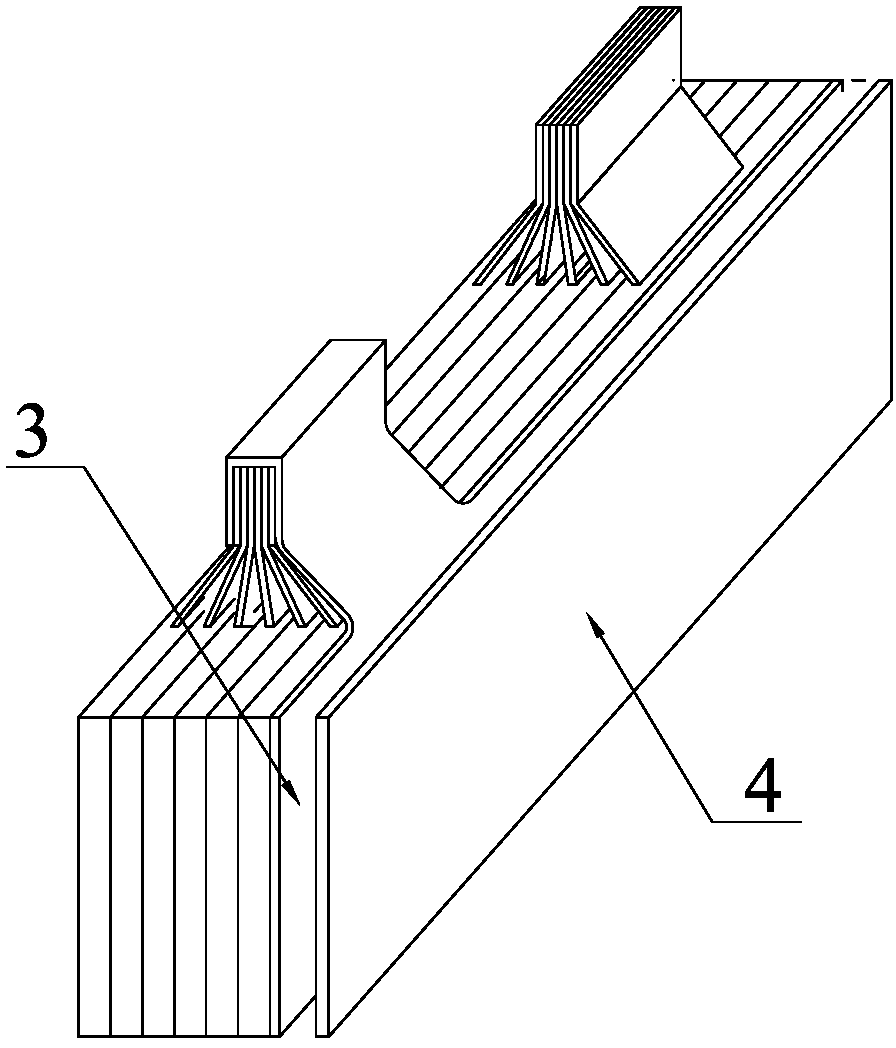
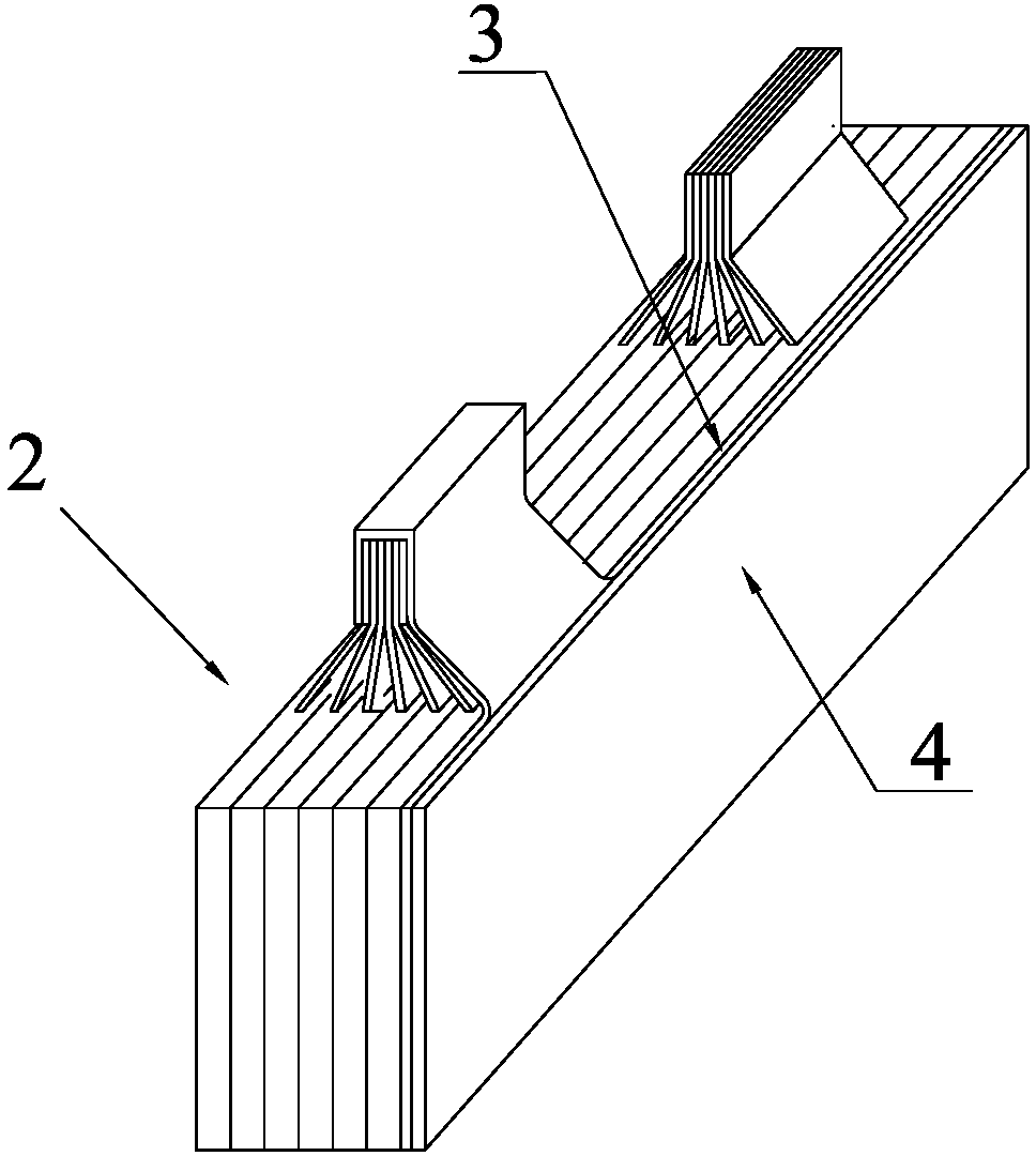
[0042] combine Figure 7 to Figure 16 , the preferred embodiments of the present invention will be described in further detail.

[0043] A large-capacity, high-output specific power polylithium battery structure includes at least two such as Figure 7 The monolithic group 2 formed by the monolithic battery pole piece 1 is shown.

[0044] The internal structure of the single-piece battery pole piece 1 is the same as that of the single-piece battery pole piece in the traditional polymer lithium-ion battery pack, and they are neatly stacked in order. The positive pole tab 11 and the negative pole tab on each single-piece battery pole piece 1 12 all correspond neatly.

[0045] In a monolithic group 2, the positive electrode tab 11 and the negative electrode tab 12 are respectively pressed and shaped, such as Figure 8shown. Due to the grouping form, the number of stacked pole pieces is small, the thickness is small, and the deformation of the tabs of the edge pole pieces is sm...


PUM

PropertyMeasurementUnit
Thicknessaaaaaaaaaa
Thicknessaaaaaaaaaa
Thicknessaaaaaaaaaa

Abstract

The invention mainly discloses a poly lithium battery structure with high capacity and high output ratio power. The poly lithium battery structure comprises a plurality of single battery pole pieces, wherein all single battery pole pieces are equally divided into a plurality of small single piece groups, polar lugs, which have same polarity, of single battery pole pieces in the same single piece group, are reshaped by pressing and clamped by a positive clamp and a negative clamp through welding; positive auxiliary electrode aluminum conductive metal sheets and polytetrafluoroethylene clapboard sheets are stacked between two adjacent groups; clamps with same polarity in each group are connected by an output connector in a unified manner; and the poly lithium battery structure is finally formed by packaging an aluminum-plastic packaging film. The poly lithium battery structure disclosed by the invention breaks through the bottleneck of application of high output ratio power and high current discharge of the traditional polymer lithium ion battery. According to the poly lithium battery structure, the accumulation of the polarization effect and the heat effect of the high-capacity battery under the condition of high output ratio power and high current discharge is greatly improved, the working temperature of the battery is reduced by 30 percent and the output capacity of the battery is improved by 38 percent than those of the traditional polymer lithium ion battery structure, the polarization effect of the battery is reduced and the temperature of a thermal runway platform is improved by 80-95 DEG C.

Description

technical field [0001] The invention relates to the technical field of high-output specific power and high-current discharge application of polymer lithium-ion batteries, in particular to a large-capacity high-output specific power polylithium battery structure. Background technique [0002] With the development of modern society, polymer lithium-ion batteries are more and more widely used in industry energy demand and application due to its excellent performance conditions. However, in the technical field of high-capacity, high-output specific power, and high-current discharge applications, for a single large-capacity battery that operates with harsh requirements (low discharge temperature and high discharge capacity ratio), due to its tab metal sheet cross-section output rated current Density and single large-capacity battery working under high output specific power and high current discharge working current density under asymmetric conditions will inevitably lead to poor ...

Claims


Application Information

Patent Timeline
IPC IPC(8): H01M2/26H01M2/16H01M10/0525
CPCY02E60/122Y02E60/10
Inventor 马军玲王雪晴
Owner 厦门太和动力电源科技有限公司
Learn More