Pneumatic opposed-piston engine

A technology of opposed pistons and compressed air pistons, which is applied to combustion engines, machines/engines, mechanical equipment, etc., can solve problems such as complex structures, and achieve high efficiency and simple structures

Inactive Publication Date: 2013-01-02
ZEROQ SCI & TECH
View PDF6 Cites 7 Cited by
  • Summary
  • Abstract
  • Description
  • Claims
  • Application Information

AI Technical Summary

Problems solved by technology

However, most of these engines are two-stroke engines. For this reason, a supercharger needs to be added to meet the requirements of starting, which inevitably makes the structure complicated. Structural features, increasing its compression fu

Method used


Image

  • Pneumatic opposed-piston engine
  • Pneumatic opposed-piston engine
  • Pneumatic opposed-piston engine

Examples


Embodiment 1

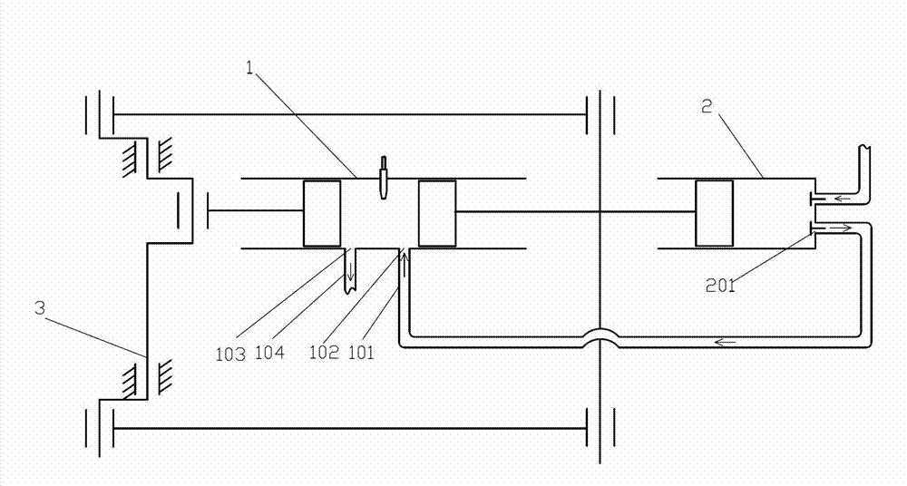
[0039] Such as figure 1 The shown compressed gas opposed piston engine comprises an internal gas cylinder 1, a compressed gas cylinder 2 and a crankshaft 3, two internal combustion pistons are oppositely arranged in one of the internal gas cylinders 1, and a compressed gas piston is arranged in the compressed gas cylinder 2, the The compression piston is connected with one internal combustion piston, one internal combustion piston in the internal gas cylinder 1 is connected to the connecting rod journal of the crankshaft 3 through a connecting rod, and the other internal combustion piston is connected to the crankshaft 3 through another connecting rod. The other connecting rod journals of the crankshaft 3 are rotatably connected, and there is a phase difference between the two types of connecting rod journals. Connected, the displacement of the compressor cylinder 2 is greater than the displacement of the internal gas cylinder 1 .

[0040] Wherein, the compressed gas piston ...

Embodiment 2

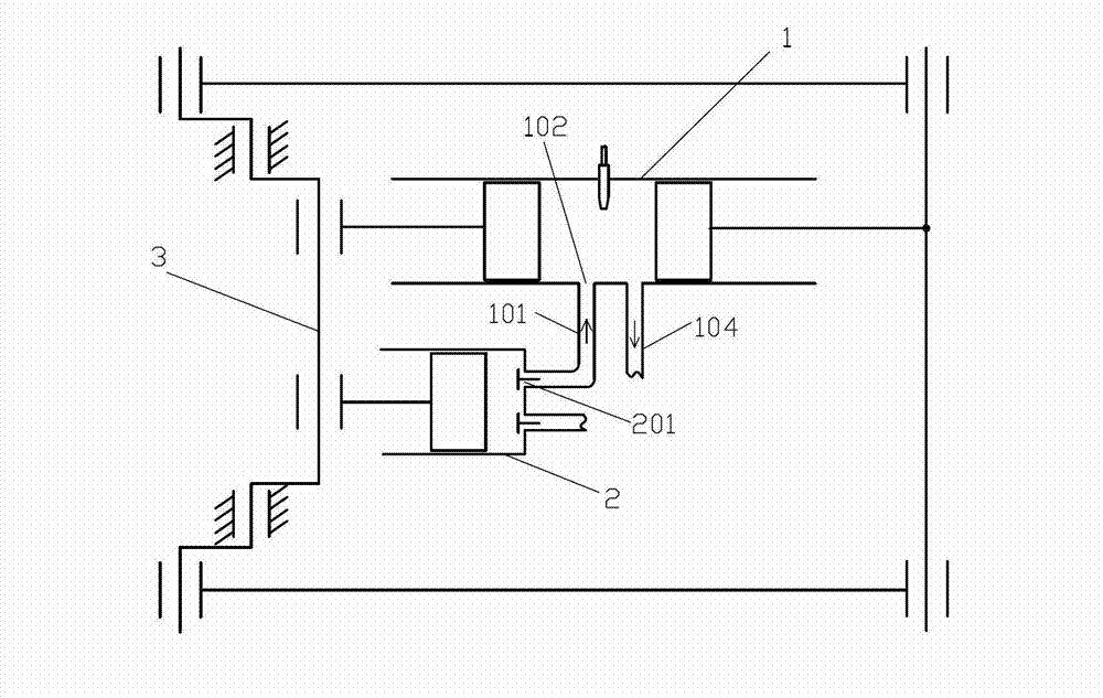
[0045] Such as figure 2 The difference between the compressed-gas opposed-piston engine shown in Embodiment 1 is that the compressed gas piston is connected to the internal combustion piston close to the crankshaft 3, wherein the internal combustion cylinder 1 and the internal combustion piston constitute The engine has a compression ratio of 8.

Embodiment 3

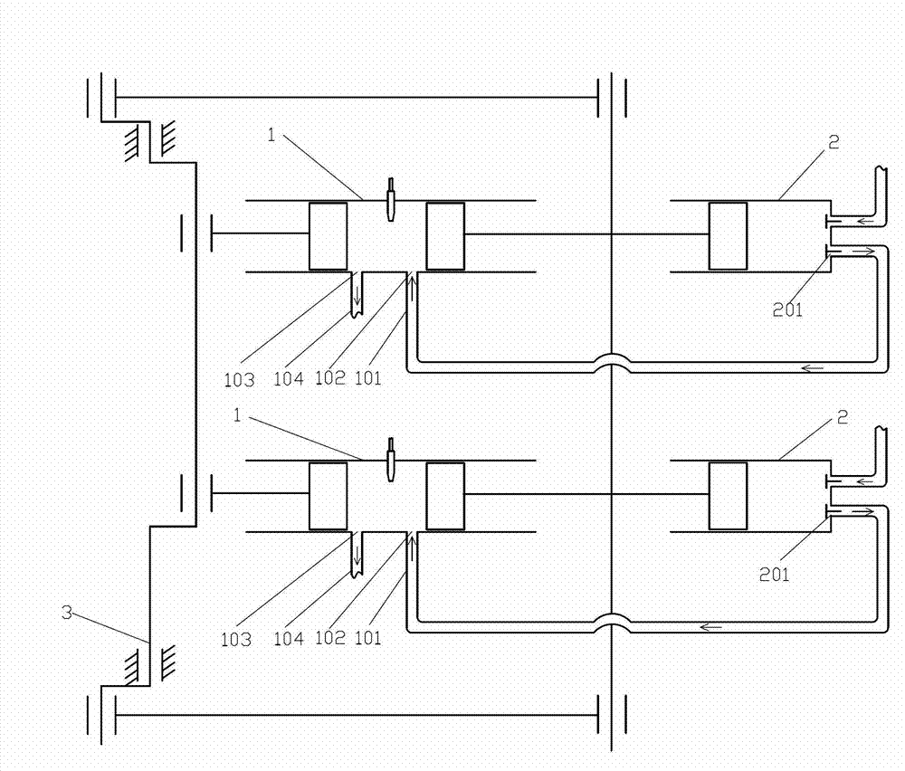
[0047] Such as image 3 The difference between the compressed air opposed piston engine and Embodiment 1 is that the compressed air opposed piston engine includes two internal gas cylinders 1 and two compressed air cylinders 2, and the two internal gas cylinders 1 are parallel It is set that two internal combustion pistons are arranged opposite to each other in each of the internal combustion cylinders 1, and the compression pistons are respectively arranged in each of the compression cylinders 2, and one of the internal combustion pistons in each of the internal gas cylinders 1 The internal combustion piston is connected with one said compression piston, and the sum of the displacements of the two compression cylinders 2 is greater than the sum of the displacements of the two internal combustion cylinders 1, and the engine formed by the internal combustion cylinder 1 and the internal combustion piston The compression ratio is 12.

[0048] Optionally, the opposed piston engin...


PUM


Abstract

The invention discloses a pneumatic opposed-piston engine which comprises internal combustion cylinders, pneumatic cylinders and a crankshaft, wherein two internal combustion pistons are arranged in one internal combustion cylinder in an opposed mode, pneumatic pistons are arranged in one pneumatic cylinder and connected with the internal combustion pistons, one internal combustion piston in the internal combustion cylinder is rotatablely connected with a rod journal of the crankshaft through a connecting rod, the other internal combustion piston is rotatablely connected with another rod journal of the crankshaft through another connecting rod, a phase difference exists between the two rod journals, a compressed gas inlet of the pneumatic cylinder is communicated with a gas inlet channel of an internal combustion engine of the internal combustion cylinder, and the displacement of one pneumatic cylinder or the displacement sum of all the pneumatic cylinders is greater than the displacement sum of all the internal combustion cylinders. The pneumatic opposed-piston engine disclosed by the invention is simple in structure and high in efficiency.

Description

technical field [0001] The invention relates to the field of thermal energy and power, in particular to an opposed piston engine. Background technique [0002] In recent years, the research and development of opposed piston engines and double opposed piston engines has become increasingly popular. However, most of these engines are two-stroke engines. For this reason, a supercharger needs to be added to meet the requirements of starting, which inevitably makes the structure complicated. Structural features, increasing its compression function and / or increasing its expansion work function is the premise of whether the working explosion pressure of the engine can be improved without excessively increasing the weight of the engine, thereby improving the efficiency of the engine. Therefore, need to invent a kind of novel opposed-piston engine. Contents of the invention [0003] In order to solve the above problems, the technical scheme proposed by the present invention is a...

Claims


Application Information

Patent Timeline
IPC IPC(8): F02B75/28F02B41/02F02B33/06
Inventor 靳北彪
Owner ZEROQ SCI & TECH
Why Eureka
Try Eureka