Method for operating an internal combustion engine

A technology for internal combustion engines and compressors, applied in the field of operating internal combustion engines, which can solve the problems of high friction turbine impeller and compressor impeller, reduce engine torque generation, unavoidable perception, etc., and achieve the effect of reliable actual value

Inactive Publication Date: 2013-01-02
GM GLOBAL TECH OPERATIONS LLC
View PDF0 Cites 6 Cited by
  • Summary
  • Abstract
  • Description
  • Claims
  • Application Information

AI Technical Summary

Problems solved by technology

During these seconds, the friction between the turbocharger shaft and its bearings is too high for the turbine and compressor wheels to rotate properly, thus causing a lack of boost pressure which causes a reduced engine torque generation
[0012] As a result, if the driver

Method used


Image

  • Method for operating an internal combustion engine
  • Method for operating an internal combustion engine
  • Method for operating an internal combustion engine

Examples


Embodiment Construction

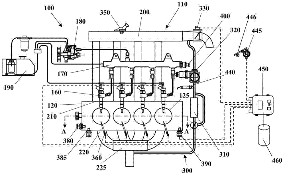
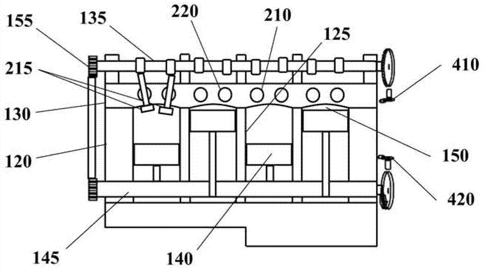
[0127] Some embodiments may include automotive systems 100 such as figure 1 and 2 As shown in , the automotive system 100 includes an internal combustion engine (ICE) 110 , in this example a diesel engine, having an engine block 120 defining at least one cylinder 125 having a piston 140 , the piston 140 is coupled to rotate a crankshaft 145 . Cylinder head 130 cooperates with piston 140 to define combustion chamber 150 . A fuel and air mixture (not shown) ignites after having been disposed in combustion chamber 150 , resulting in thermal expansion of exhaust gases causing reciprocation of piston 140 . Fuel is provided by at least one fuel injector 160 and air is provided through at least one intake port 210 . Fuel is provided to fuel injector 160 at high pressure from fuel rail 170 in fluid communication with high pressure fuel pump 180 which increases the pressure of fuel received from fuel source 190 . Each cylinder 125 has at least two valves 215 actuated by a camshaft ...


PUM


Abstract

A method for operating an internal combustion engine (110) is provided. The method includes ascertaining an actual value (T) of an operating temperature of the internal combustion engine (110). An electrically driven compressor (600) located in an intake pipe (205) of the internal combustion engine is activated if the actual value (T) of the operating temperature of the internal combustion engine is below a threshold value (T_th) thereof.

Description

technical field [0001] The invention relates to a method of operating an internal combustion engine, primarily an internal combustion engine of a motor vehicle. More specifically, the invention relates to a method of operating an internal combustion engine shortly after start-up. Background technique [0002] Known internal combustion engines generally comprise an engine block comprising a plurality of cylinders each housing a reciprocating piston and closed by a cylinder head cooperating with the pistons to define an internal combustion chamber. The pistons are mechanically coupled to the engine crankshaft such that reciprocating motion of each piston is translated into rotation of the engine crankshaft due to combustion of fuel in a corresponding combustion chamber. [0003] Lubrication systems are provided to lubricate the rotating and sliding parts of internal combustion engines. Oil systems generally include an oil pump that draws oil from an oil sump and delivers it ...

Claims


Application Information

Patent Timeline
IPC IPC(8): F02D41/00F02D41/30
CPCF02B37/11F02D41/405F02D41/064F02D41/0007F02D41/068F02B39/10F02D2200/0406F02B37/04F02D2200/021Y02T10/144F02D23/02F02D2200/023Y02T10/12
Inventor C.M.米诺G.巴索
Owner GM GLOBAL TECH OPERATIONS LLC
Why Eureka
Try Eureka