Inertia sensing apparatus

A technology of inertial sensing and inertial motion, applied in measuring devices, microstructure devices, surveying and navigation, etc., can solve problems affecting the accuracy of acceleration sensing, difficulty in detecting capacitance sensing circuits, and reduction of capacitance change values, etc., to achieve Effects of improving sensing accuracy, increasing mass asymmetry, and reducing area

Inactive Publication Date: 2013-01-02
SENSORTEK TECH
View PDF3 Cites 12 Cited by
  • Summary
  • Abstract
  • Description
  • Claims
  • Application Information

AI Technical Summary

Problems solved by technology

As the size shrinks, the difference caused by the mass asymmetry of the Z-axis accelerometer will not be obvious, so that the displacement of the mass block decreases and the capacitance change value decreases, which makes it difficult for the capacitance sensing circuit to detect
[0006] And another way to increase the output signal is to increase the mass of the accelerometer, and use a larger mass block to simultaneously sense the acceleration values ​​of the three axes. Today's acceleration sensing device 1' has three accelerometers Integrated together, and three accelerometers are connected together to increase the efficiency of sensing, but because the three accelerometers are connected together, it is easy to generate noise because the three will affect each other, which will affect the accuracy of its acceleration sensing Spend

Method used


Image

  • Inertia sensing apparatus
  • Inertia sensing apparatus
  • Inertia sensing apparatus

Examples


Embodiment Construction

[0036] In order to make the structural features of the present invention and the achieved effects have a further understanding and recognition, preferred embodiments and detailed descriptions are specially used, which are described as follows:

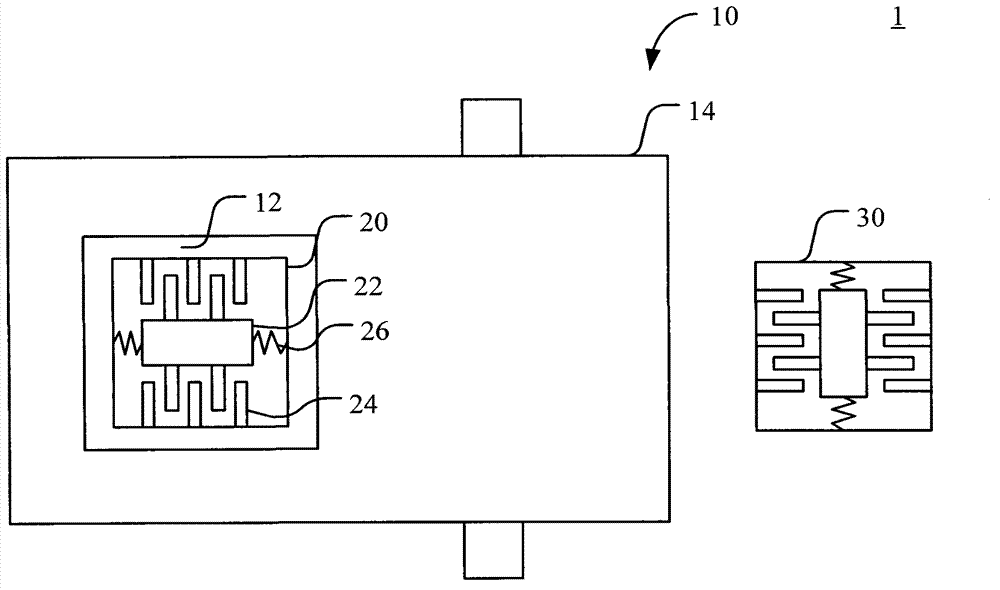
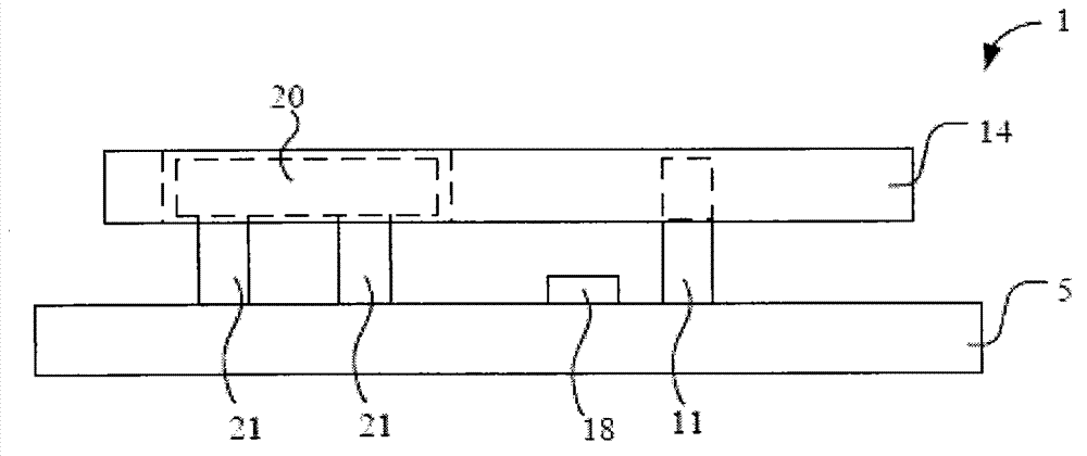
[0037] see figure 2 , Figure 3A and Figure 3B , is a structural schematic diagram, a front view and a schematic action diagram of a preferred embodiment of the present invention. As shown in the figure, the inertial sensing device 1 of the present invention includes a substrate 5 , a first inertial sensing unit 10 and a second inertial sensing unit 20 . The first inertial sensing unit 10 is connected to the substrate 5 and has an accommodating space 12 , the second inertial sensing unit 20 is connected to the substrate 5 and is arranged in the accommodating space 12 of the first inertial sensing unit 10 Inside, except that the first inertial sensing unit 10 and the second inertial sensing unit 20 are respectively connected to the...


PUM


Abstract

The invention relates to an inertia sensing apparatus, comprising a substrate, a first and second inertia sensing elements. The first inertia sensing element is connected to a substrate and has a containment space. The second inertia sensing element is connected to the substrate and is disposed in the containment space of the first inertia sensing element, wherein the first inertia sensing element and the second sensing element are connected to the substrate, and the first inertia sensing element and the second sensing element are not connected to each other, the first inertia sensing element and the second sensing element individually and independently detect at least one inertia motion of the inertia sensing apparatus. Therefore, the invention is based on the second inertia sensing element disposed in the containment space of the first inertia sensing element and they individually and independently detect at least one inertia motion of the inertia sensing apparatus, so as to decrease an area of the inertia sensing apparatus, thus reducing the chip size and prevent the two inertia sensing elements from coupling to result in decreasing the sensing precision.

Description

technical field [0001] The invention relates to an inertial sensing device, in particular to an inertial sensing device which can save the overall chip area and improve sensing accuracy. Background technique [0002] In today's consumer electronics industry, in order to improve the functions of electronic products, it is necessary to provide a sensing device capable of accurately measuring inertial motion, such as an inertial sensing unit for the physical quantity of acceleration or angular velocity. In general, acceleration in any direction and angular velocity in any direction of rotation act on an object freely moving in three-dimensional space. Therefore, in order to accurately grasp the motion of the object, it is necessary to measure the acceleration along each coordinate axis of the XYZ three-dimensional coordinate system and the angular velocity around each coordinate axis. Therefore, there is a need for an inertial sensing device having a compact size and high prec...

Claims


Application Information

Patent Timeline
Patent Type & Authority Applications(China)
IPC IPC(8): G06F3/0346
CPCG01P2015/084G01P15/00G06F1/1694B81B3/0062G01C19/5733G01C21/16G01P2015/082G01P15/125G01P2015/0845G01P15/18G01P2015/0848G01C19/5783G01C21/166
Inventor 林烔彣翁焕翔吴嘉昱
Owner SENSORTEK TECH
Why Eureka
Try Eureka