Bandpass wave-transmitting material and antenna housing and antenna system

A wave-transparent, non-metallic material technology, applied in the field of radome, can solve the problems of poor wave-transmission performance, and achieve the effects of enhanced wave-transmission performance, reduced restrictions, and enhanced radiation capabilities

Active Publication Date: 2015-07-15
KUANG CHI CUTTING EDGE TECH LTD
View PDF1 Cites 0 Cited by
  • Summary
  • Abstract
  • Description
  • Claims
  • Application Information

AI Technical Summary

Problems solved by technology

[0004] The technical problem to be solved by the present invention is to provide a band-pass wave-transparent material and its radome and antenna system for the above-mentioned defects of the prior art with poor wave-transmitting performance

Method used


Image

  • Bandpass wave-transmitting material and antenna housing and antenna system
  • Bandpass wave-transmitting material and antenna housing and antenna system
  • Bandpass wave-transmitting material and antenna housing and antenna system

Examples


Embodiment Construction

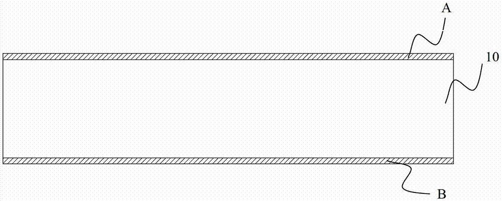
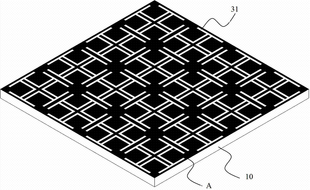
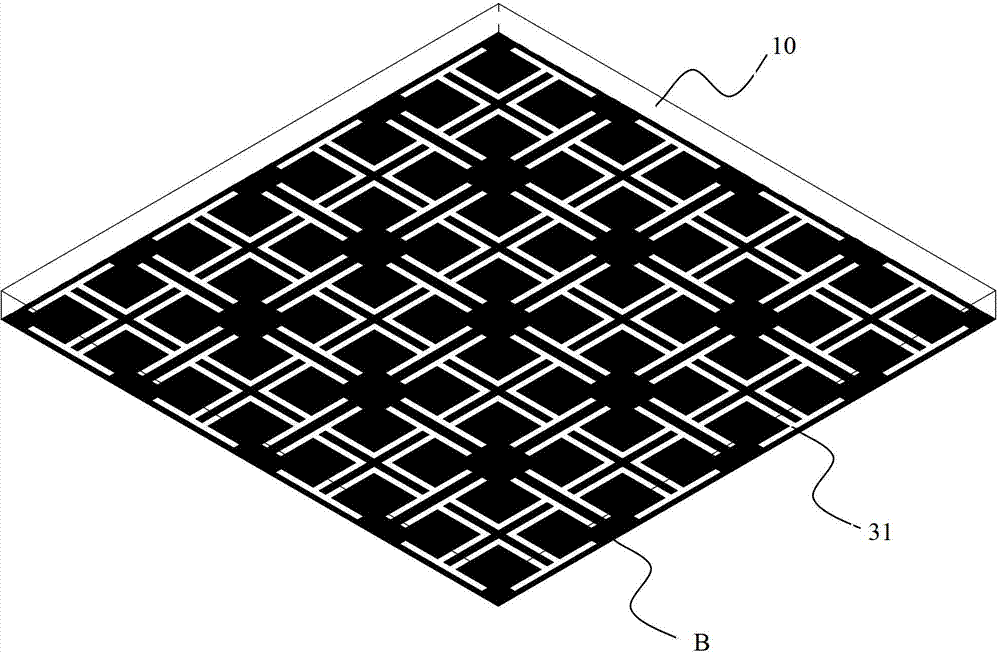
[0027] The invention provides a material with a transparent wave, such as Figure 1~2 shown. The wave-transparent material includes a first substrate 10 made of a non-metallic material, and a plurality of artificial microstructures 31 attached to two opposite outer surfaces of the first substrate 10 and arranged in an array. Adjacent artificial microstructures 31 There is no gap between them, and a plurality of artificial microstructures form two layers of artificial microstructure layers A and B on the two opposite outer surfaces. Such as figure 2 As shown, the artificial microstructure is a square patch with a snowflake-shaped groove structure, and a cross-shaped structure is also arranged in the snowflake-shaped groove structure. The cross-sectional view of the wave-transparent material is shown in figure 1 .

[0028] It can be understood that the number of artificial microstructures shown in the accompanying drawings is only for illustration, and is used to illustrate...


PUM


Abstract

The invention relates to a bandpass wave-transmitting material, and an antenna housing and an antenna system. The bandpass wave-transmitting material comprises a first substrate produced by non-metal materials, and a plurality of artificial micro-structures which are attached to two opposite outer surfaces of the first substrate and distributed in an array manner, and no clearance exists between the adjacent artificial micro-structures; and each artificial micro-structure is a square paster provided with a snowflake-shaped notch structure, and a cross-shaped structure is also arranged in the snowflake-shaped notch structure. The bandpass wave-transmitting material, the antenna housing and the antenna system can be high in wave transmittance in work frequency range, and can shield other frequency ranges, thus eliminating interference and ensuring the good working environment of an antenna. The antenna housing is arranged on the antenna, the radiation capability of the antenna is enhanced, and the gain is effectively improved.

Description

technical field [0001] The present invention relates to a radome, and more particularly, to a band-transparent wave-transparent material, a radome and an antenna system therefor. Background technique [0002] Generally, the antenna system is provided with a radome. The purpose of the radome is to protect the antenna system from wind, rain, snow, sand and solar radiation, so that the performance of the antenna system is relatively stable and reliable. At the same time, it reduces the wear, corrosion and aging of the antenna system and prolongs its service life. However, the radome is an obstacle in front of the antenna, which will absorb and reflect the radiated waves of the antenna, change the free space energy distribution of the antenna, and affect the electrical performance of the antenna to a certain extent. [0003] At present, the materials for making radome are mostly materials with low dielectric constant and loss tangent and high mechanical strength, such as fiber...

Claims


Application Information

Patent Timeline
Patent Type & Authority Patents(China)
IPC IPC(8): H01Q15/02H01Q1/42
Inventor 刘若鹏赵治亚方小伟付少丽
Owner KUANG CHI CUTTING EDGE TECH LTD
Why Eureka
Try Eureka