Control device for motor drive system and vehicle having same

A technology of motor drive and control device, which is applied in the direction of controlling electromechanical transmission device, power consumption device, motor generator control, etc. to achieve the effect of improving efficiency

Active Publication Date: 2013-01-02
DENSO CORP
View PDF9 Cites 7 Cited by
  • Summary
  • Abstract
  • Description
  • Claims
  • Application Information

AI Technical Summary

Problems solved by technology

However, in such a case, when the motor rotates at a high speed, there is a possibility that the induced voltage (counter electromotive force) of the motor generated by the magnet is greater than the input voltage of the inverter driving the motor

Method used


Image

  • Control device for motor drive system and vehicle having same
  • Control device for motor drive system and vehicle having same
  • Control device for motor drive system and vehicle having same

Examples


Embodiment approach 1

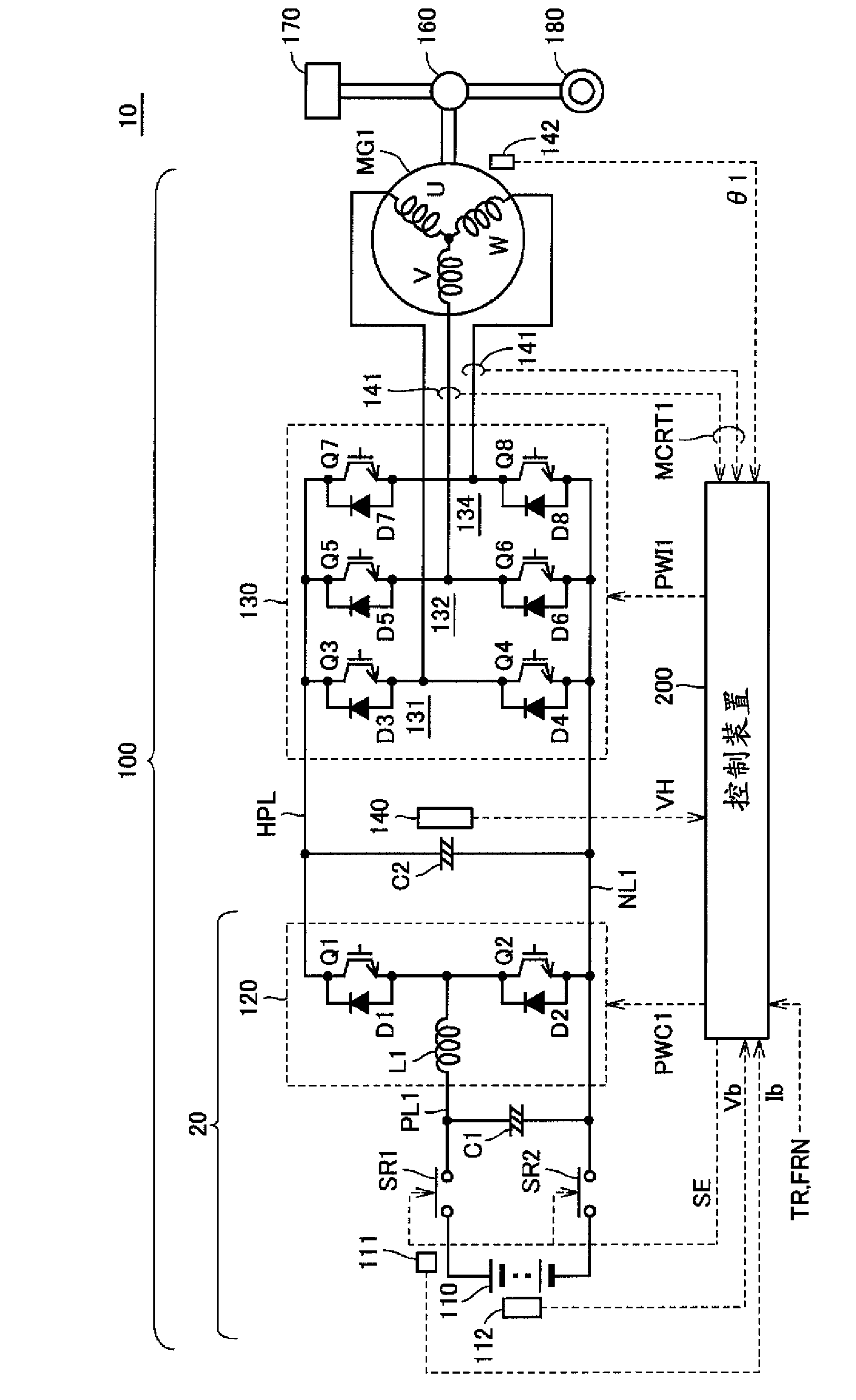
[0101] In such a motor drive system, in order to increase the rotation speed or output of AC motor MG1 as described above, it is necessary to increase the system voltage VH. However, the system voltage VH cannot be set arbitrarily high, and is basically limited by the withstand voltage (withstand voltage) of devices such as converters and / or converters.

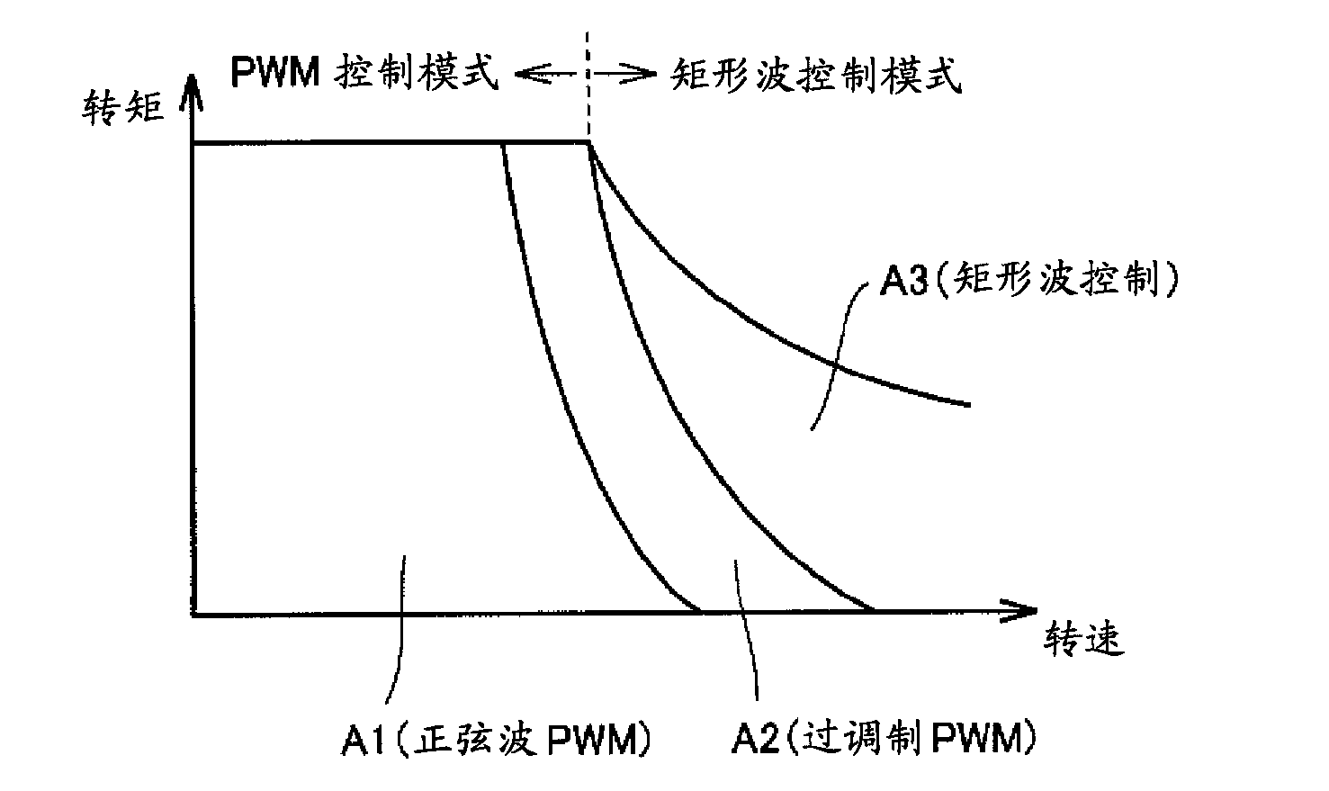
[0102] Figure 4 versus image 3 Similarly, it is a graph showing the relationship between the rotation speed MRN1 of the AC motor MG1 and the torque command value TR. in Figure 4 Here, the curve W2 shows the critical value at which the system voltage VH becomes the maximum value.

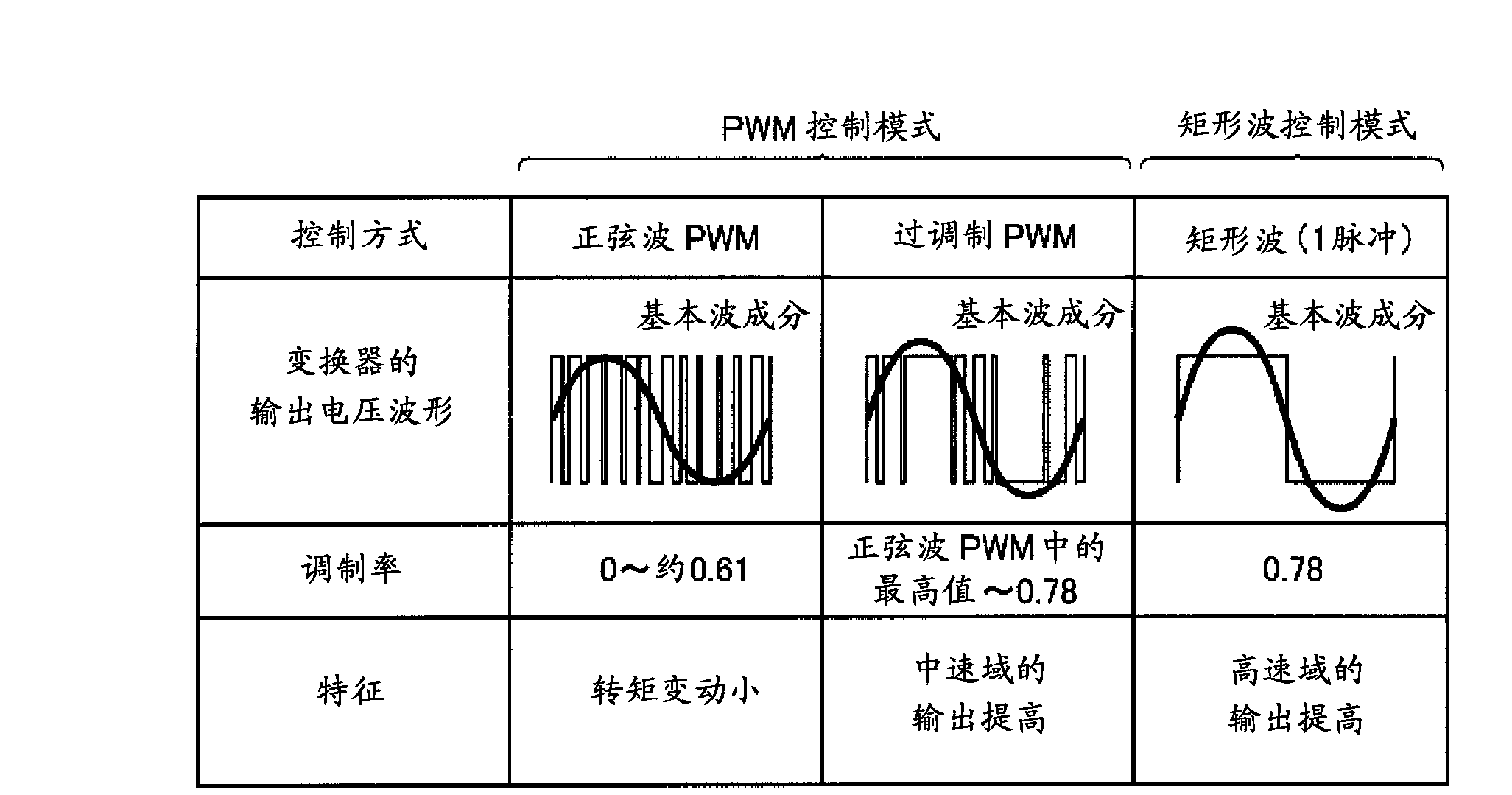
[0103] That is, the low speed side or low output side of the curve W2 is a region where the system voltage VH is variable. In this region, through the above-mentioned PWM control (sine wave PWM control and overmodulation PWM control), it is possible to control the motor to apply voltage. Size to get the desired speed and output torque. However, on t...

Embodiment approach 2

[0139] In the first embodiment, the following method is described: in the case of a low torque command, with respect to the maximum value Vdc of the system voltage VH, the boost command value is increased by easing the voltage variation caused by the control variation, so that The field weakening control area moves to the high-speed side to improve efficiency.

[0140] In the second embodiment, the following method is described. Furthermore, by considering the magnitude of the current flowing in the converter and the converter, the amount of voltage fluctuation due to the switching surge generated when the converter and the converter are switched is explained. , To increase the boost command value, thereby further improving efficiency.

[0141] Figure 13 versus Image 6 with Figure 7 It is also a diagram showing the withstand voltage of the inverter and the switching elements included in the converter. In the second embodiment, in addition to ΔV1 which is the amount of voltage f...

Embodiment approach 3

[0151] In the first and second embodiments, the following method is described: in the case of a low torque command, the maximum value Vdc of the system voltage VH is alleviated with respect to the amount of voltage fluctuation due to control fluctuations and switching surges, Increase the boost command value.

[0152] In the third embodiment, the following method will be described: especially when the torque command value is almost zero, the current flowing in the AC motor becomes very small, so that the switching operation is stopped and the system voltage VH is not performed. limits.

[0153] Figure 17 It is a diagram for explaining the outline content of Embodiment 3, which is similar to that in Embodiment 1 and Embodiment 2. Figure 7 with Figure 13 Similarly, a diagram showing the withstand voltage of the converter and the switching elements included in the converter.

[0154] Reference Figure 17 In the first and second embodiments, although the voltage fluctuation ΔV1 cause...


PUM


Abstract

A control device (200) for a motor drive system (100) including an AC motor (MG1) having a magnet on a rotor, a converter (120) and an inverter (130), generates a boost command value for the converter (120) on the basis of a torque command value of the AC motor (MG1). The control device (200) determines whether weak field control, which increases the current in the direction in which the magnetic force supplied to the AC motor (MG1) from the inverter (130) is diminished, is to be implemented, on the basis of the boost command value and the drive status of the AC motor (MG1). If weak field control is to be implemented, and the absolute value of the torque command value is smaller than a threshold value, the control device (200) will further increase the generated boost command value. As a result of doing so, the level of the weak field current can be reduced, thereby improving the efficiency of the motor drive system (100).

Description

Technical field [0001] The present invention relates to a control device for a motor drive system and a vehicle equipped with the control device, and more specifically, to a motor drive control that reduces loss in a motor drive system capable of performing field weakening control. Background technique [0002] In recent years, as an environmentally friendly vehicle, a vehicle that is equipped with a power storage device (for example, a secondary battery, a capacitor, etc.) and that uses the driving force generated by the electric power stored in the power storage device has attracted attention. Such vehicles include, for example, electric vehicles, hybrid vehicles, and fuel cell vehicles. [0003] These vehicles generally have a motor in order to generate driving force from the electric power stored in the power storage device. As this motor, a permanent magnet type synchronous motor (PM motor) in which permanent magnets are embedded in the rotor is sometimes used. In such a PM ...

Claims


Application Information

Patent Timeline
Patent Type & Authority Applications(China)
IPC IPC(8): H02P27/02H02P6/08B60L9/18H02M3/155H02M7/48H02P6/17H02P6/28H02P21/22H02P23/30H02P25/026H02P27/06H02P27/08
CPCH02P23/004Y02T10/643H02P21/0089H02P23/009B60L15/20B60L15/08Y02T10/644Y02T10/642H02P2201/07B60L2220/14B60L15/2045H02P23/30Y02T10/64Y02T10/72
Inventor 冈村贤树高松直义
Owner DENSO CORP
Why Eureka
Try Eureka