Control device for motor drive system and vehicle equipped with the control device
A motor drive and control device technology, applied in the field of motors, to achieve the effect of improving efficiency
- Summary
- Abstract
- Description
- Claims
- Application Information
AI Technical Summary
Problems solved by technology
Method used
Image
Examples
Embodiment approach 1
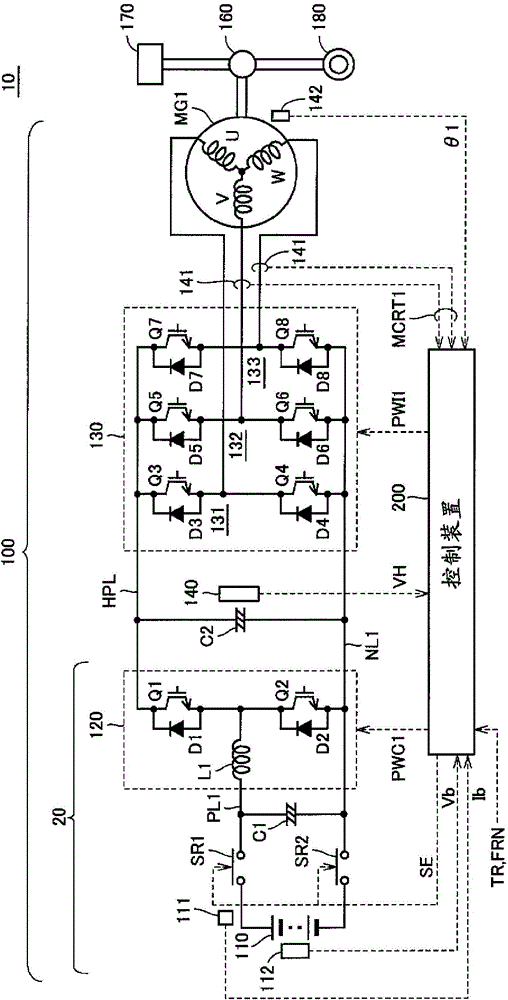
[0101] In such a motor drive system, in order to increase the rotational speed or output of AC motor MG1 as described above, it is necessary to increase system voltage VH. However, the system voltage VH cannot be set arbitrarily high, and is basically limited by the withstand voltage (withstand voltage, withstand voltage) of devices such as converters and / or converters.
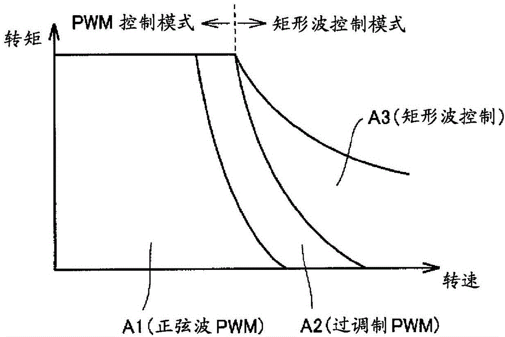
[0102] Figure 4 and image 3 Similarly, it is a graph showing the relationship between the rotational speed MRN1 of the AC motor MG1 and the torque command value TR. exist Figure 4 In , the curve W2 shows the critical value at which the system voltage VH becomes the maximum value.
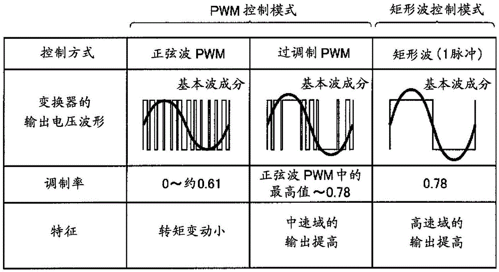
[0103] That is, the low rotation speed side or low output side of the curve W2 is a region where the system voltage VH is variable, and in this region, the above-mentioned PWM control (sine wave PWM control and overmodulation PWM control) can control the voltage applied to the motor. Size to get the desired speed and output ...
Embodiment approach 2
[0139] In Embodiment 1, a method of increasing the voltage boost command value by mitigating the amount of voltage variation due to control variation with respect to the maximum value Vdc of the system voltage VH in the case of a low torque command, so that The field weakening control area is moved to the high speed side to improve efficiency.
[0140] In Embodiment 2, the following method will be described. Furthermore, by considering the magnitude of the current flowing through the inverter and the converter, the amount of voltage variation due to the switching surge generated when the inverter and the converter perform switching operations will be described. , to increase the boost command value, thereby further improving efficiency.
[0141] Figure 13 and Figure 6 and Figure 7 It is also a graph showing the breakdown voltage of the inverter and switching elements included in the converter. In the second embodiment, the maximum value Vdc of the system voltage VH is m...
Embodiment approach 3
[0151] In Embodiment 1 and Embodiment 2, the method of mitigating the maximum value Vdc of the system voltage VH against the amount of voltage variation due to control fluctuations and switching surges in the case of a low torque command, Increase boost command value.
[0152] In Embodiment 3, a method of stopping the switching operation without changing the system voltage VH by taking advantage of the fact that the current flowing through the AC motor is very small in a state where the torque command value is substantially zero is described. limits.
[0153] Figure 17 is a diagram for explaining the outline of Embodiment 3, and is the same as that in Embodiment 1 and Embodiment 2 Figure 7 and Figure 13 Similarly, a graph of the withstand voltage of the inverter and switching elements included in the inverter is shown.
[0154] refer to Figure 17 , in Embodiment 1 and Embodiment 2, although the voltage fluctuation ΔV1 caused by the control fluctuation and the voltage ...
PUM
 Abstract
Description
Claims
Application Information
 - R&D
- Intellectual Property
- Life Sciences
- Materials
- Tech Scout
- Unparalleled Data Quality
- Higher Quality Content
- 60% Fewer Hallucinations
Browse by: Latest US Patents, China's latest patents, Technical Efficacy Thesaurus, Application Domain, Technology Topic, Popular Technical Reports.
© 2025 PatSnap. All rights reserved.Legal|Privacy policy|Modern Slavery Act Transparency Statement|Sitemap|About US| Contact US: help@patsnap.com


