Detachable or cuttable connecting rod and application thereof to spine surgical operation

A technology of connecting rods and together, which is applied in the application field of spinal surgery to achieve the effects of multi-activity, convenient operation and economical cost saving

Inactive Publication Date: 2013-01-09
SHANGHAI CHANGZHENG HOSPITAL
View PDF5 Cites 2 Cited by
  • Summary
  • Abstract
  • Description
  • Claims
  • Application Information

AI Technical Summary

Problems solved by technology

But there is no report about a detachable or shearable connecting rod for spinal surgery

Method used


Image

  • Detachable or cuttable connecting rod and application thereof to spine surgical operation
  • Detachable or cuttable connecting rod and application thereof to spine surgical operation
  • Detachable or cuttable connecting rod and application thereof to spine surgical operation

Examples


Embodiment 1

[0038] Embodiment 1 The connecting rod that can be cut off one

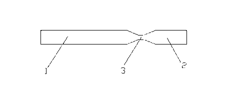
[0039] Please refer to the attached figure 1 , with figure 1 It is a structural schematic diagram of a shearable connecting rod 1 of the present invention. The first connecting rod includes a tail end 1 and a head end 2 of the connecting rod. There is a notch 3 on the first connecting rod, and the tail end 1 of the connecting rod and the head end 2 of the connecting rod are connected together through the notch 3 .

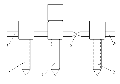
[0040] Please refer to the attached figure 2 , with figure 2 It is a use state diagram of a cut-off connecting rod 1 of the present invention. It should be noted that during the operation, the connecting rod can be cut off through the gap 3, the head end 2 of the connecting rod can be removed, and the pedicle screw 8 at the head end on the head end 2 of the connecting rod can be taken out.

[0041] In the intraoperative reduction process of spondylolisthesis, the connecting rod of the present...

Embodiment 2

[0043] Embodiment 2 Detachable connecting rod 2

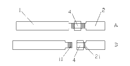
[0044] Please refer to the attached image 3 , with image 3It is a structural schematic diagram of a detachable connecting rod 2 of the present invention, A is a structural schematic diagram of the connecting rod 2, and B is a schematic diagram of the structure decomposition of the connecting rod 2. The second connecting rod includes a connecting rod tail end 1 and a connecting rod head end 2 , and the connecting rod tail end 1 and connecting rod head end 2 are fixed together by bolts 4 . Please refer to image 3 B, the tail end 1 of the connecting rod is provided with a tail end thread 11, the head end 2 of the connecting rod is provided with a head end thread 21, the tail end thread 11 and the head end thread 21 have the same diameter and pitch, and are fixed on the Together.

[0045] Please refer to the attached Figure 4 , with Figure 4 It is a use state diagram of a detachable connecting rod 2 of the present inve...

Embodiment 3

[0046] Example 3 Detachable connecting rod three

[0047] Please refer to the attached Figure 5 , with Figure 5 is a schematic diagram of the structure of a detachable connecting rod 3 of the present invention, A is a schematic diagram of the structure of the connecting rod 3, and B is a schematic diagram of the structure decomposition of the connecting rod 3. The connecting rod three includes a connecting rod tail end 1 and a connecting rod head end 2, the connecting rod tail end 1 and the connecting rod head end 2 are fixed together by internal and external threads, and the connecting rod tail end 1 is provided with There is a tail end internal thread 12, and the head end 2 of the connecting rod is provided with a head end external thread 22, the head end external thread 22 is inserted into one end of the connecting rod tail end 1, and the head end external thread 22 and the tail end internal thread 12 are screwed tightly , so that the tail end 1 of the connecting rod ...


PUM


Abstract

The invention relates to a detachable or cuttable connecting rod. The connecting rod comprises a connecting rod head end and a connecting rod tail end; and the connecting rod head end and the connecting rod tail end can be separated by a disassembling or cutting mode. The invention also relates to application of the connecting rod. The connecting rod has the advantages that the connecting rod has simple structure, is convenient to operate and is suitable to widely apply to the lumbar spondylolisthesis reduction and the scoliosis orthopedic operation; the connecting rod is of a cuttable or detachable structure, and thus, not only can the connecting rod be used as a stable supporting lever for reduction when the lumbar spondylolisthesis reduction is carried out, but also two residual pedicle screws can be taken out after the reduction is completed, so that a normal intervertebral space is avoided being fixedly fused and more lumbar motion ranges are kept; when the scoliosis orthopaedics is carried out, the connecting rod has a better effect of correcting the rotatory deformity of the scoliosis, the normal intervertebral space is also avoided fixedly fused and more spinal motion ranges are kept; and the economic cost can be saved by adopting the method.

Description

technical field [0001] The invention relates to the field of medical instruments, in particular to a detachable or cut-off connecting rod for spinal surgery and its application in spinal surgery. Background technique [0002] At present, scoliosis is corrected by using pedicle screw technology. Usually, the most distal fixation point is generally the lower end vertebra in the stable area or 1-2 vertebral bodies distal to the lower end vertebra. Scoliosis is usually accompanied by rotational deformity, and the lower end vertebra at the farthest end of the fixation range or 1-2 vertebrae beyond the lower end vertebra is usually accompanied by a certain degree of rotational deformity. When bending, because the distal fixed point still has different degrees of rotational deformity, and there is a lack of a distal counterpoint without rotational deformity, the orthopedic effect of rotation is not good. Fixing one more vertebral body can provide a better counterpoint for correcti...

Claims


Application Information

Patent Timeline
IPC IPC(8): A61B17/70
Inventor 袁文吴晓东陈华江王新伟周许辉杨立利
Owner SHANGHAI CHANGZHENG HOSPITAL
Why Eureka
Try Eureka