Positioning and clamping mechanism for a plurality of drill holes

A technology for positioning and clamping and positioning keys, which is used in positioning devices, clamping, metal processing mechanical parts, etc., can solve the problems of low equipment utilization, high work intensity, and high equipment costs, reducing work intensity and improving processing efficiency. , the effect of improving the processing capacity

Inactive Publication Date: 2013-01-09
TENGXUAN TECH
View PDF10 Cites 27 Cited by
  • Summary
  • Abstract
  • Description
  • Claims
  • Application Information

AI Technical Summary

Problems solved by technology

Drilling with a scribing drill machine manually has problems such as high work intensity, large dimensional error, and low work efficiency.
Although the machining center clamping can ensure high dimensional accuracy and reduce work intensity, it has problems such as low equipment utilization rate and high equipment cost.

Method used


Image

  • Positioning and clamping mechanism for a plurality of drill holes
  • Positioning and clamping mechanism for a plurality of drill holes
  • Positioning and clamping mechanism for a plurality of drill holes

Examples


Embodiment Construction

[0014] The present invention will be further described below in conjunction with specific drawings and embodiments.

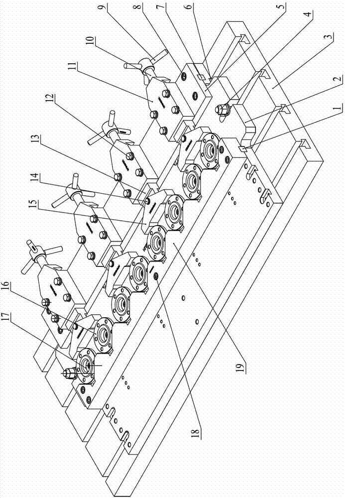
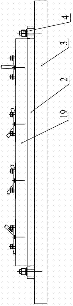
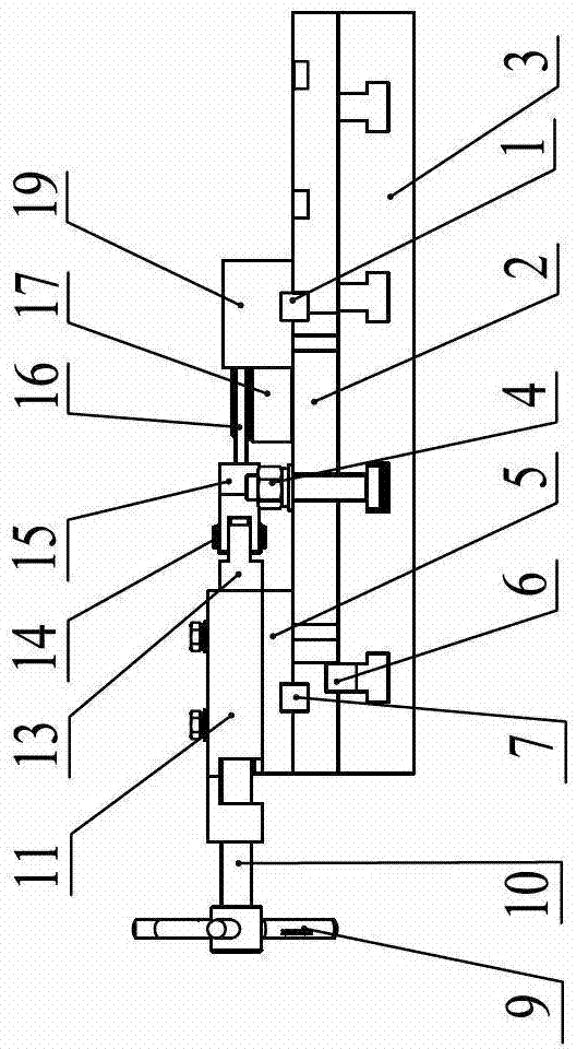
[0015] As shown in the figure: the multi-piece drilling positioning and clamping mechanism in the embodiment is mainly composed of a first positioning key 1, a clamp body 2, a machine tool table 3, a T-bolt 4, a backing plate 5, a second positioning key 6, and a second positioning key 6. Three positioning key 7, screw 8, handle 9, compression bolt 10, support body 11, bolt 12, push plate 13, cylindrical pin 14, pressure plate 15, workpiece 16, positioning plate 17, screw 18 and fixed V-shaped block 19 and other components.

[0016] like Figure 1~Figure 4 As shown, the clamp body 2 cooperates with the T-shaped groove in the machine table 3 through the second positioning key 6 and locks it with the T-shaped bolt 4; the backing plate 5 cooperates with the positioning groove on the clamp body 2 through the third positioning key 7 and locks it. The screw 8 is loc...


PUM


Abstract

The invention relates to a positioning and clamping mechanism for a plurality of drill holes. A clamp body is matched and locked with a T-shaped groove in a machine table through a second positioning key; a cushion plate is matched and locked with a positioning groove on the clamp body through a third positioning key; a fixing V-shaped block is matched and locked with the positioning groove on the clamp body through a first positioning key; a plurality of V-shaped grooves on the fixing V-shaped block is used for placing workpieces to be machined; a plurality of supporting bodies are arranged side by side and corresponding to a plurality of V-shaped grooves on the fixing V-shaped block, the supporting bodies are respectively locked on the cushion plate, a slideable pushing plate is installed in each supporting body respectively; the front end of the pushing plate is hinged with a compressing plate through a columnar pin, a compressing bolt is installed in the supporting body; the front end of the compressing bolt is connected with the pushing plate, the rear end of the compressing bolt is equipped with a handle; a rotating handle can drive the compressing bolt to drive the pushing plate to glide in the supporting body forwards; the workpiece to be machined is completely compressed in the fixing V-shaped block. The positioning and clamping mechanism is simple and practical in structure, flexible in operation and good in interchangeability.

Description

technical field [0001] The invention relates to a tooling structure for multi-piece clamping, drilling, positioning and clamping of parts of the same type and specification, in particular to a multi-piece drilling, positioning and clamping mechanism, which belongs to the technical field of mechanical processing equipment. Background technique [0002] In the manufacturing process of rotary joints, the end face porous processing of disc parts is completed by conventional metal cutting. For example, a fitter drills a line or uses a drilling template to complete it on a drilling machine. At present, the more advanced method is to complete the porous processing in the machining center through the three-jaw clamping of the chuck. Drilling with a scribing drill machine manually has problems such as high work intensity, large dimensional error, and low work efficiency. Although the machining center clamping can ensure high dimensional accuracy and reduce work intensity, it has pr...

Claims


Application Information

Patent Timeline
Patent Type & Authority Applications(China)
IPC IPC(8): B23Q3/06
Inventor 丁飏沈元坤季新
Owner TENGXUAN TECH
Why Eureka
Try Eureka