
Bow and arrow testing machine

A technology for testing machines and bows and arrows, which is applied in the field of sports equipment, and can solve the problems of not being able to meet the requirements at one launch site, insufficient adjustment range of launch pitch angle, and inability to test recurve bows, etc.

Inactive Publication Date: 2013-01-09
吴速军
View PDF6 Cites 2 Cited by
  • Summary
  • Abstract
  • Description
  • Claims
  • Application Information

AI Technical Summary

Problems solved by technology

Due to the structural limitations of this archery machine, the bow can only be opened by shaking the rocker arm in the form of a winch. It is difficult to perform front and rear fine-tuning at any position during the bow opening process, and due to the insufficient adjustment range of the launch pitch angle, it is necessary to test low-weight equipment at a long distance. At the same time, the demand cannot be met at one launch site, and because the front and rear legs directly touch the ground, the machine has to be manually moved to a suitable launch position
The most important thing in the testing process of bows and arrows is to obtain accurate pulling force and drawing distance. However, since this kind of archery machine is a winch-type bow that is shaken manually, it is difficult to repeat the test efficiently when the testing equipment is unchanged and the drawing distance is fixed. and precise repeat positioning, and cannot directly read the tension data and obtain the tension curve on the machine
The "Fire Pig" archery machine does not have the ability to test recurve bows. Its hanging bow assembly and outriggers are fixed, which cannot cope with the level adjustment problem when the ground is uneven.

Method used


Image

  • Bow and arrow testing machine
  • Bow and arrow testing machine
  • Bow and arrow testing machine

Examples


Embodiment Construction

[0034] The present invention will be further explained in conjunction with the drawings:

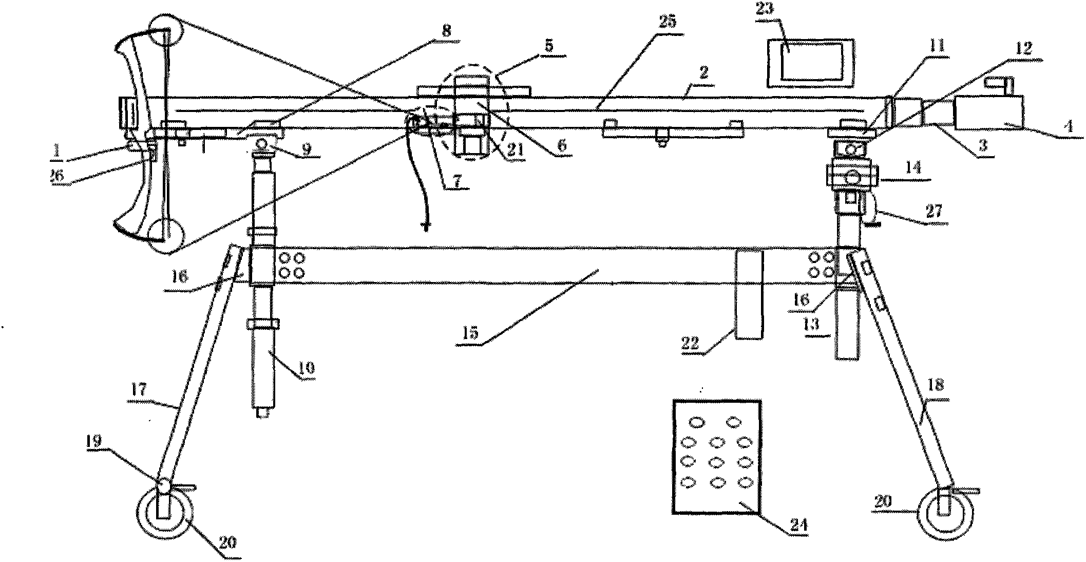
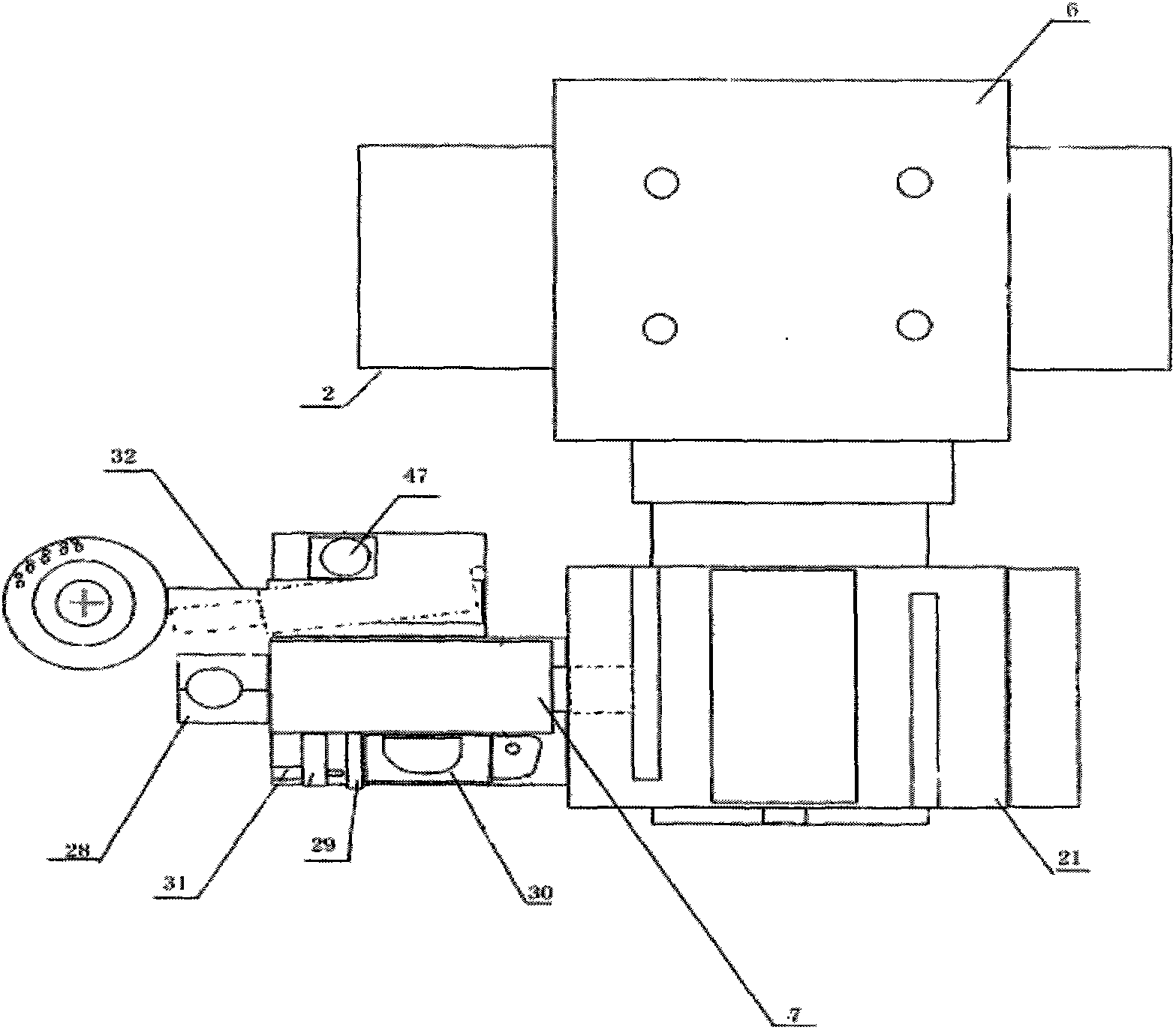
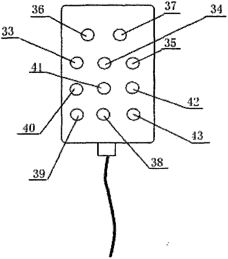
[0035] Such as figure 1 As shown, it is a schematic diagram of the bow opening state of a bow and arrow testing machine, including the bow hanging frame 1 at the front end of the linear motion unit 2, and the tail end of the linear control unit 2 is connected to the servo motor 4 through the coupling 3. The component 5 is connected to the linear motion unit 2 through the bow opening assembly connecting block 6; the spreading assembly 7 is located at the front end of the bow opening assembly 5; the lower position of the front of the linear motion unit 2 passes through the front base 8 and the front pitch The adjustment joint 9 is connected to the front column 10, and the lower position of the rear part is connected to the horizontal angle fine adjustment platform 14 on the rear column 13 through the rear base 11 and the rear pitch adjustment joint 12; the front end position of the main beam 1...


PUM


Abstract

The invention discloses a bow and arrow testing machine to eliminate the defects existing in the use of traditional bow and arrow testing machines, which are unable to effectively test relevant performances of a recurve bow and must be moved constantly in order to implement relevant tests when being used in situations, for example, the ground is uneven, the distance needs to be changed or the like, thus bringing unnecessary troubles to users. Compared with the traditional bow and arrow testing machines, the bow and arrow testing machine in the invention is provided with a hanging bow assembly level adjustment device and pitching angle adjustment structures built in front and back upright posts so that the trouble that the machine have to be moved constantly for objective reasons can be overcome. Meanwhile, the testing machine disclosed by the invention is equipped with a recurve bow shooting effect simulation suite specially used for testing the performances of a recurve bow, and when testing the performances of a recurve bow, what needs to do is to carry out test in a normal way after the suite is installed, thereby bringing great convenience to users.

Description

Technical field [0001] The invention belongs to the field of sports equipment, and particularly relates to a bow and arrow testing machine, which can freely adjust the pitch angle and the horizontal angle according to needs, and can test the performance of composite bows, recurve bows and other equipment. Background technique [0002] At present, the international test of bows and arrows mainly uses an American-made "Fire Pig" archery machine, which consists of a manual winch, a shutter release mechanical release, a screw-type pitch, a horizontal manual adjustment mechanism and front and rear outriggers, The main beam is composed. Due to the structural limitation of this archery machine, the bow can only be opened by swinging the rocker arm in the way of a winch. It is difficult to fine-tune the front and back at any position during the bowing process, and due to the insufficient adjustment range of the launching pitch angle, it is necessary to test low-weight equipment from a di...

Claims


Application Information

Patent Timeline
IPC IPC(8): G01M5/00
Inventor 吴速军
Owner 吴速军
Learn More