
Design method of grating with glaring concave surface

A technology of blazed grating and design method, applied in diffraction grating and other directions, can solve the problem that the blaze effect of concave blazed grating is not very obvious, and achieve the effect of significant blaze enhancement effect and convenient implementation.

Inactive Publication Date: 2013-01-09
UNIV OF SHANGHAI FOR SCI & TECH
View PDF1 Cites 12 Cited by
  • Summary
  • Abstract
  • Description
  • Claims
  • Application Information

AI Technical Summary

Problems solved by technology

[0003] The invention aims at the problem that the blazed effect of the concave blazed grating on a specific wavelength is not obvious, and proposes a design method of the concave blazed grating

Method used


Image

  • Design method of grating with glaring concave surface
  • Design method of grating with glaring concave surface
  • Design method of grating with glaring concave surface

Examples


Embodiment Construction

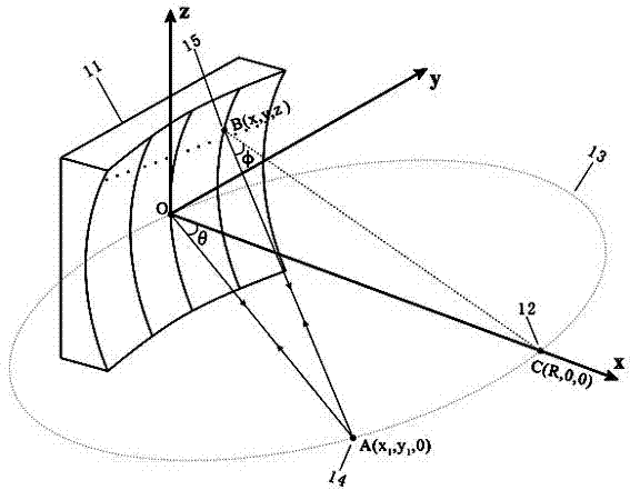
[0015] figure 1 Shown is the optical path diagram for the use of concave blazed gratings. 11 is a concave blazed grating, its radius of curvature is R, 12 is its center of curvature C (R,0,0), and 13 is a Rowland circle, which is a concave spherical surface whose diameter is equal to the radius and is tangent to the concave spherical surface at point O (0 ,0,0), at the same time, the circle is located in the main section xOy plane, 14 is the incident point A (x 1 ,y 1 , 0), the incident angle of the central ray is θ, 15 is any point B (x, y, z) on the concave spherical surface, and x, y, z satisfy the equation (x-R) 2 +y 2 +z 2 =R 2 .

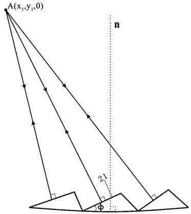
[0016] figure 2 is a local enlarged view of the groove surface of the concave blazed grating. For any point B on the concave spherical surface, its normal line n passes through the curvature center of the concave surface, that is figure 1 BC in; on the other hand, in order to improve the efficiency of the grating, it is required that a...


PUM


Abstract

The invention relates to design method of a grating with a glaring concave surface. For a concave substrate with the preset radius R, carving grooves with preset angles and intervals are carved on the substrate so as to obtain the grating with the glaring concave surface. Incident light is spherical wave sent out by a point light source, the point light source is located on a Rowland circle, angles of curving groove surfaces are designed so as to enable the incident light to be perpendicular to the carving groove surfaces, the interval of the carving grooves is designed so as to enable optical path difference of adjacent carving grooves to be integral multiple of preset wavelength, carving grooves with corresponding angles and interval are carved one by one on the concave substrate by using a free curved-surface processing instrument, and the required grating with the glaring concave surface is obtained. The designed concave grating has remarkable glaring enhancement effect on the preset wavelength lambda, the design method is convenient to implement, only relates to calculation of elementary mathematics, dose not need professional optical design software, and the designed grating with the glaring concave surface can be widely applied to the technical field of a spectrum analysis instrument, optical detection, optical measurement and the like.

Description

technical field [0001] The invention relates to the design of an optical instrument, in particular to a design method of a concave blazed grating. Background technique [0002] Diffraction gratings are widely used in the fields of spectral analysis, lasers, integrated optical circuits, optical communications, industrial control and metrology as optical splitting elements with superior performance. For example, in spectroscopic instruments, gratings are key components that require extremely high precision. , Gratings have almost completely replaced prisms and are used as dispersion elements of spectroscopic instruments. The development of precision grating manufacturing technology directly affects the development of other scientific and technological fields such as geology, metallurgy, astronomy, medicine, and aerospace, and its role is immeasurable. Most of the energy of the incident light on a common grating is concentrated on the zero-order diffraction order without disper...

Claims


Application Information

Patent Timeline
Patent Type & Authority Applications(China)
IPC IPC(8): G02B5/18
Inventor 徐邦联黄元申卢忠荣张大伟倪争技王琦陶春先庄松林
Owner UNIV OF SHANGHAI FOR SCI & TECH
Learn More