Eureka AIR delivers breakthrough ideas for toughest innovation challenges, trusted by R&D personnel around the world.

Quasi-close loop starting method of brushless direct current motor free of position sensor

A brushed DC motor and sensor technology, applied in the field of mechanical engineering, can solve problems such as out-of-step, back EMF zero-crossing detection cannot be effectively detected, and the rotor position cannot be predicted

Inactive Publication Date: 2013-01-09
CENTRAL SOUTH UNIVERSITY OF FORESTRY AND TECHNOLOGY
View PDF3 Cites 38 Cited by
  • Summary
  • Abstract
  • Description
  • Claims
  • Application Information

AI Technical Summary

Problems solved by technology

The traditional three-stage starting method is to complete the positioning of the rotor position in the static state of the motor, and then use the external synchronous starting method to energize the motor windings in sequence according to the set order. At this time, the motor rotor is dragged in the rotating magnetic field generated by the windings. Generally speaking, the position of the rotor is in a hysteresis state. When the motor is unloaded, the hysteresis position is small and the success rate of starting is high. Being dragged, or severely out of sync
Both of these situations are due to the fact that the back EMF zero-crossing detection cannot be effectively detected at the initial stage of start-up, resulting in unpredictable rotor position, and the system is completely working in an open-loop state.
In the open-loop state, the system often fails to energize the accurate winding at the exact time, and cannot guarantee that the motor rotor can obtain effective torque, resulting in the failure of the motor to start

Method used


Image

  • Quasi-close loop starting method of brushless direct current motor free of position sensor
  • Quasi-close loop starting method of brushless direct current motor free of position sensor
  • Quasi-close loop starting method of brushless direct current motor free of position sensor

Examples


Embodiment 1

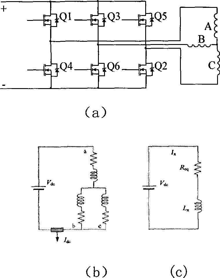
[0109] The sensorless brushless DC motor control system test platform consists of a brushless DC motor body, a DSP (TMS3202812) control board, a power drive board, a magnetic powder brake, and measuring instruments. During the test, the H_PWM-L_PWM modulation method is adopted, the PWM modulation carrier frequency is 20KHz, the positioning detection pulse period is set to 10μs, and the motor parameters are shown in Table 7. The magnetic powder brake is the load of the motor test system. The excitation current of 0.1A is passed into the magnetic powder brake, that is, the load torque is set to 1N.m.

[0110] Table 7 Motor parameters

[0111]

[0112] After measuring the equivalent time constant of the motor is 10μs, in this example the period of the short pulse voltage vector is 10μs. Figure 8 The starting waveform of the quasi-closed-loop starting mode proposed by the present invention is adopted when the rotating speed of the motor test platform is set to 2000rpm. Figu...


PUM


Abstract

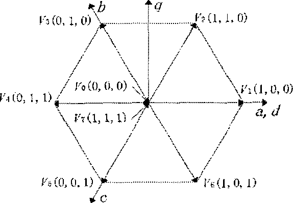
The invention discloses a quasi-close loop starting method of a brushless direct current motor free of a position sensor, namely a quasi-close loop three-stage starting method with rotor initial position accurate pre-positioning and optimization positioning in the acceleration process combined. Short-time pulse voltage vectors are exerted in a motor winding, the rotor position can be locked in a range within 60-degree electrical angles by detecting direct-current bus current, and rotor accurate pre-positioning is completed by electrifying a designated winding, detecting current and comparing the current on the basis of rotor position locking. After rotor position pre-positioning, rotors enter the optimization positioning and acceleration stage, current differentials serve as the phase change conditions in the threshold range so that the rotors are ensured to change phase accurately in the acceleration process, and a system is switched into a counter electromotive force operation state. Experimental results show that the quasi-close loop three-stage starting method is low in cost and high in reliability, and can ensure that the system is in the quasi-close loop working state in the whole starting process and cannot have step-out and starting failure.

Description

technical field [0001] The invention belongs to the field of mechanical engineering and relates to a quasi-closed-loop starting method for a brushless DC motor without a position sensor. Background technique [0002] Brushless DC motors use high magnetic energy rare earth permanent magnet materials, which have the characteristics of small size, light weight, high efficiency, and low loss. They have been widely used in aviation, aerospace, machinery, automobiles and other industrial fields. Usually, brushless DC motors generally use position sensors to determine the position of the motor rotor, but the installation of position sensors increases system cost, increases system complexity, reduces system reliability and anti-interference ability, and these problems will directly increase the complexity of the production process , and some even seriously affect the service life of the system, so the sensorless brushless DC motor control technology has become a hot research topic t...

Claims


Application Information

Patent Timeline
IPC IPC(8): H02P21/00
Inventor 朱俊杰
Owner CENTRAL SOUTH UNIVERSITY OF FORESTRY AND TECHNOLOGY
Why Eureka
Eureka Blog
Learn More