
Compensation light source system and dynamic image detecting device for train operation fault

A technology for compensating light sources and optical fibers, applied in the field of lasers, it can solve the problems of limited rail space, incompatibility, and camera exposure effects, and achieve the effects of improving utilization, increasing light intensity, and improving laser utilization.

Active Publication Date: 2013-01-16
BWT BEIJING
View PDF9 Cites 4 Cited by
  • Summary
  • Abstract
  • Description
  • Claims
  • Application Information

AI Technical Summary

Problems solved by technology

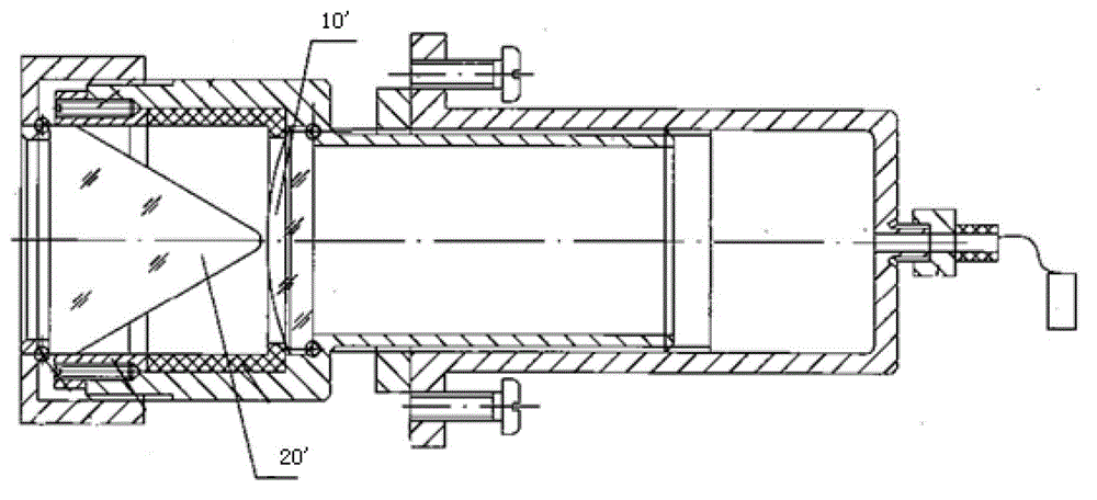
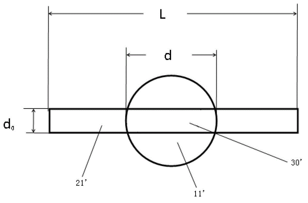
If the width d of the projected portion 21' is increased 0 , then it is necessary to increase the radius of curvature of the projection part 21', which will cause the divergence angle of the laser beam passing through the prism 20' to decrease, and then cause the length of the light spot irradiated on the object to be photographed to be incompatible with the length of the object to be photographed
If the diameter d of the circular light spot 11' is reduced, the width of the light spot refracted by the prism 20' will be too small to meet the scanning width requirement of the camera, which will affect the exposure of the camera
[0007] Regardless of whether it is a convex lens or a concave lens, when the radius of curvature becomes smaller, the optical aberration of the same beam after refraction will become larger, so the quality of the spot will be uneven
In the prior art, a round lens is used in the front, and a prism is used in the back. The width of the finally formed elongated light is determined by the front round lens, and the length is determined by the back prism. If it is too large, part of the light cannot be refracted, and the light utilization rate is low. If the light spot is reduced so that the entire light spot can irradiate the curved surface, the width of the light spot is not enough
Moreover, according to the design in the prior art, in order to achieve a divergence angle of 60 degrees, the radius of curvature is already very small. At this time, the aberration is very large. If the divergence angle is to be increased, the radius of curvature must be smaller, so that the prism behind will become more slender, and the problems described above will be more prominent
[0008] Therefore, the technical solution disclosed in this patent application cannot ensure a high laser utilization rate while ensuring that the spot shape meets the camera shooting requirements
At the same time, since the divergence angle of the laser beam passing through the prism 20' is only 60 degrees, when shooting under the vehicle, the length of the light spot is not enough due to the short distance, so it is often necessary to set two or more lasers in a row. The space is limited, and it is difficult to realize the process
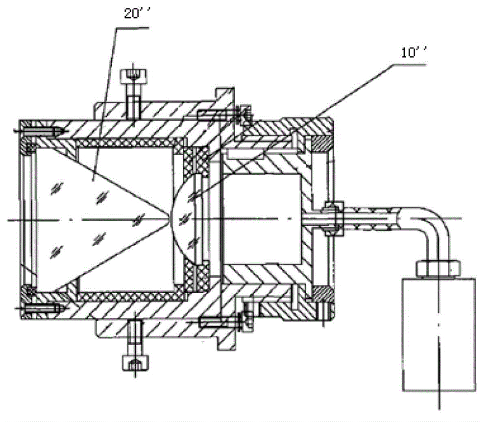
[0009] see in conjunction image 3 , is a kind of near-parallel divergent laser disclosed in the Chinese patent application with the publication number CN 201966484 U, comprising a circular lens 10 "and a prism 20", since the light spot irradiated on the prism 20 "through the circular lens 10" is still It is a circular spot, which is the same as the technical solution of the previous patent application, and it cannot guarantee a high laser utilization rate while the spot shape meets the camera shooting requirements

Method used


Image

  • Compensation light source system and dynamic image detecting device for train operation fault
  • Compensation light source system and dynamic image detecting device for train operation fault
  • Compensation light source system and dynamic image detecting device for train operation fault

Examples


Embodiment Construction

[0045] The present invention will be described in detail below with reference to the accompanying drawings and examples. It should be noted that, in the case of no conflict, the embodiments in the present application and the features in the embodiments can be combined with each other.

[0046] Such as Figure 4 As shown, according to an embodiment of the present invention, a compensation light source system is provided, including a laser generating device 50 with an optical fiber 51 and a beam shaping component. Wherein the laser generating device 50 is used for emitting laser beams. The optical fiber 51 has an optical output end, and the laser beam transmits from the optical output end after a certain distance is transmitted in the optical fiber 51 .

[0047] The beam shaping component is used to adjust the divergence angle of the laser beam so that the spot formed by the final projection of the laser beam meets the requirements of use. The beam shaping component includes ...


PUM


Abstract

The invention provides a compensation light source system and a dynamic image detecting device for a train operation fault. The compensation light source system comprises a laser generator (50) provided with an optical fiber (51) provided with an optical output end, and a beam shaping component. The beam shaping component comprises a cylindrical planoconvex lens (80) and a cylindrical planoconcave lens (90). The cylindrical planoconvex lens (80) and the optical output end of the optical fiber (51) are arranged oppositely, the cylindrical planoconcave lens (90) and the cylindrical planoconvex lens (80) are arranged sequentially along the transmission direction of laser beams transmitted by the optical output end of the optical fiber (51), and a bus of the cylindrical planoconcave lens (90) and a bus of the planoconvex lens (80) are perpendicular to each other. The compensation light source system and the dynamic image detecting device for the train operation fault have increased light utilization rate and allow light spots finally formed to meet the shooting requirements of a camera.

Description

technical field [0001] The invention relates to the field of laser technology, in particular to a compensation light source system and a dynamic image detection device for train operation faults. Background technique [0002] In order to ensure the safety of the train, it is necessary to detect the train. The efficiency of the traditional manual detection method is very low. At present, the fault dynamic image detection system is often used to take images of the bottom of the train and the side wall of the train, and then inspectors use the computer to browse the pictures taken for fault detection. The method of capturing images is mostly carried out by camera array or high-speed industrial line scan camera. No matter which method is used, it is necessary to compensate the light source to reduce the influence of the environment, such as sunlight, improve the anti-interference ability of the camera, and ensure the stable operation of the detection system. [0003] The curre...

Claims


Application Information

Patent Timeline
IPC IPC(8): G02B27/09G03B15/05G01M17/08
Inventor 刘玉凤陈晓华叶银
Owner BWT BEIJING
Learn More