High-efficiency concentrating photovoltaic cell chip

A technology of concentrating photovoltaics and cells, which is applied in the field of solar power generation, can solve the problems of reduced processing yield, easy-to-fuse negative electrodes, and low rated current, and achieve the goals of improving conversion efficiency, improving production yield, and increasing light-receiving area Effect

Inactive Publication Date: 2013-01-16
成都聚合科技有限公司
View PDF4 Cites 5 Cited by
  • Summary
  • Abstract
  • Description
  • Claims
  • Application Information

AI Technical Summary

Problems solved by technology

At present, all concentrated photovoltaic cells are based on the light intensity of 1000W / m 2 Tested and mass-produced at room temperature, the width of the negative electrode is within 0.5mm, so its rated current is relatively small, and it is easy to fuse the negative electrode under the conditions of large concentration multiples and strong light intensity.
At the same time, when welding or binding processing on both sides of the battery surface, the wire ends of the connecting wires exceeding 200um will enter the effective area of ​​the concentrating photovoltaic cells, and if the relative area of ​​the concentrating photovoltaic negative electrode is larger, the concentrating photovoltaic receiving light The area will be smaller, which will greatly reduce the conversion efficiency of concentrated photovoltaic cells
Since the concentrating photovoltaic cells are very thin, if the number of wire bonding is increased during the processing, it is easier to cause cracks and cracks in the concentrating photovoltaic cells, which will lead to a decrease in processing yield.

Method used


Image

  • High-efficiency concentrating photovoltaic cell chip
  • High-efficiency concentrating photovoltaic cell chip

Examples


Embodiment Construction

[0014] The present invention will be further described below in conjunction with the accompanying drawings.

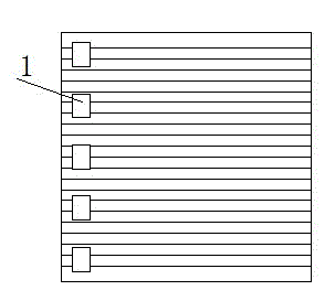
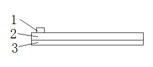
[0015] A concentrated photovoltaic cell, such as Figure 1~2 As shown, one side of the substrate layer 2 of the concentrated photovoltaic cell is the positive electrode layer 3 , and the other side is the negative electrode segment layer 1 .

[0016] The substrate layer 2 of the concentrated photovoltaic cell combines the positive electrode layer 3 and multiple negative electrode segment layers 1 skillfully through a special process, which can ensure that large currents are smoothly guided through the positive electrode layer 3 and the negative electrode segment layer 1 At the same time, it can also ensure that each electrode layer and connecting wire can withstand the rated current of 10~50 amperes.

[0017] The negative electrode segment layer 1 is processed on the substrate layer 2 of the concentrator photovoltaic cell. The negative electrode segment layer 1 ha...


PUM


Abstract

The invention relates to a high-efficiency concentrating photovoltaic cell chip, and belongs to the technical field of solar power generation. The cell chip comprises a plurality of negative electrode section layers, a concentrating photovoltaic cell substrate layer and a positive electrode layer, wherein the positive electrode layer and a plurality of negative electrode section layers are skillfully combined together through the concentrating photovoltaic cell substrate layer by a special process. High current can be smoothly led out through the positive electrode layer and the negative electrode section layers, and the cell chip is not damaged under the condition of more than 1,000 concentrating times and the regional condition of strong light; the damage probability of the cell chip during processing is reduced, so that production yield is improved; and meanwhile, by arranging the I-shaped negative electrode section layers of the cell chip, a light receiving area is effectively increased, and the aim of improving the conversion efficiency of the cell chip is fulfilled.

Description

technical field [0001] The invention relates to a photovoltaic power generation component, in particular to a high-efficiency concentrating photovoltaic battery sheet, which belongs to the technical field of solar power generation. Background technique [0002] Generally, the main benefit sought by high-power concentrated photovoltaic photoelectric conversion receivers is to obtain high-density solar radiation concentrated from Fresnel lenses on the effective area of ​​concentrated photovoltaic cells. The higher the multiple of the lens, the higher the density of solar radiation, and the fewer concentrated photovoltaic cells used on the same area, the lower the power generation cost per unit area. [0003] As the lens magnification increases, the intensity of light concentrated on the concentrated photovoltaic cells increases, and the current converted from the concentrated photovoltaic cells increases. At present, all concentrated photovoltaic cells are based on the light ...

Claims


Application Information

Patent Timeline
Patent Type & Authority Applications(China)
IPC IPC(8): H01L31/0224
Inventor 王永向
Owner 成都聚合科技有限公司
Why Eureka
Try Eureka