Control method and device for unit power factor flyback converter in critical continuous mode

A critical continuous mode, unit power factor technology, applied in the direction of output power conversion device, DC power input conversion to DC power output, control/regulation system, etc., can solve the problem of power factor and total harmonic distortion, switch tube conduction Increased pass-through loss, failure to obtain unit power factor, etc., to achieve the effect of small total harmonic distortion and high efficiency

Inactive Publication Date: 2013-01-16
SOUTHWEST JIAOTONG UNIV
View PDF3 Cites 29 Cited by
  • Summary
  • Abstract
  • Description
  • Claims
  • Application Information

AI Technical Summary

Problems solved by technology

The discontinuous mode flyback power factor corrector can obtain unity power factor, but its peak current is very large, which increases the conduction loss of the switch tube and affects the efficiency of the converter
The traditional critical continuous mode flyback power factor corrector, its control method is as follows figure 1 as shown, figure 2 For the waveforms of the primary current, secondary current and input current, the conduction time is fixed within a power frequency cycle. Although the efficiency is higher than that of the discontinuous mode flyback power factor corrector, the unit power factor cannot be obtained. Both power factor and total harmonic distortion are worse than discontinuous mode flyback power factor correctors

Method used


Image

  • Control method and device for unit power factor flyback converter in critical continuous mode
  • Control method and device for unit power factor flyback converter in critical continuous mode
  • Control method and device for unit power factor flyback converter in critical continuous mode

Examples


Embodiment Construction

[0020] The present invention will be further described in detail through specific examples and in conjunction with the accompanying drawings.

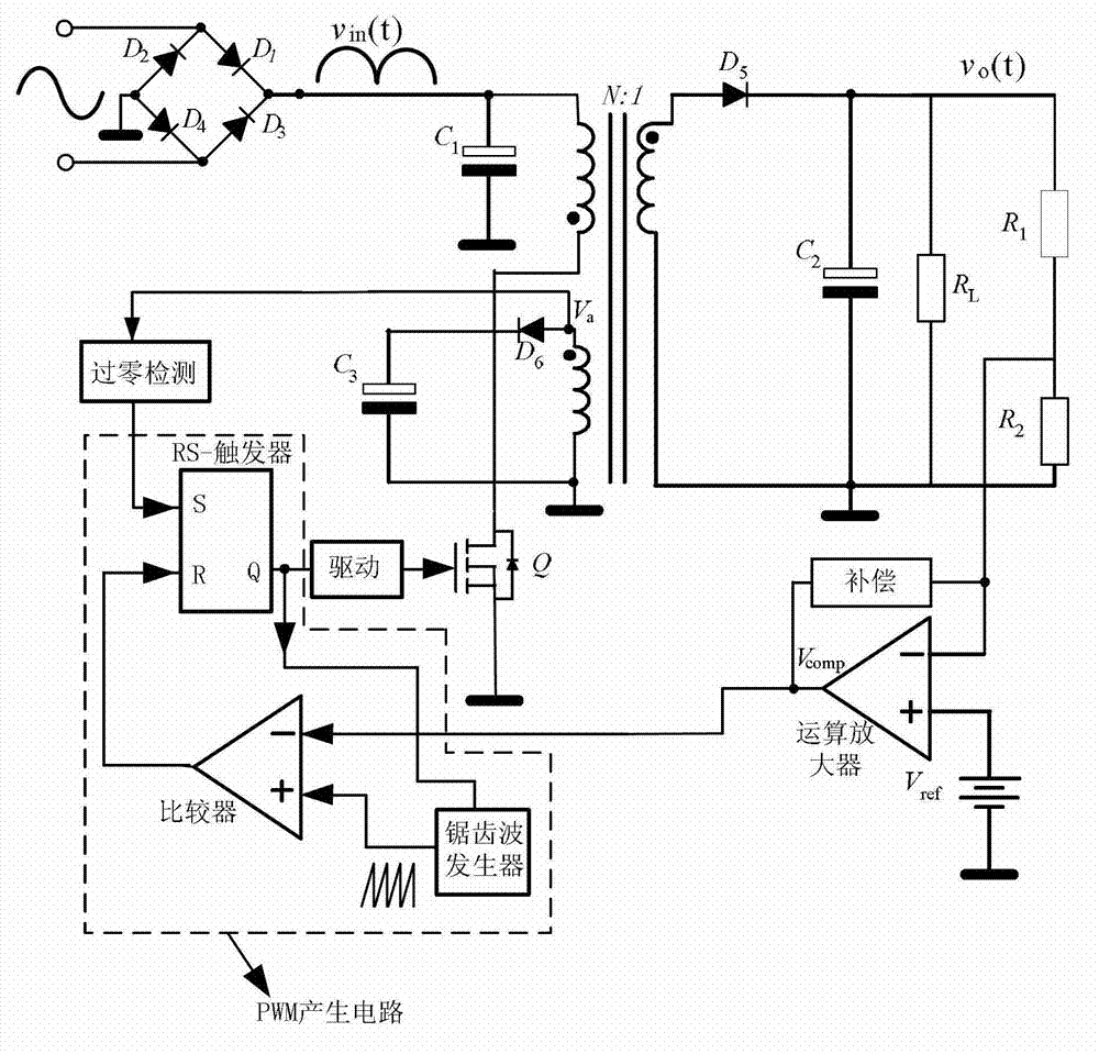
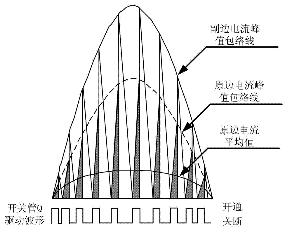
[0021] image 3 It is a structural block diagram of the present invention, Figure 4 for image 3 The main waveform diagram of the circuit is shown. From the waveform diagram, it can be known that the flyback converter works in the critical continuous mode, and the conduction time of the switch tube changes with the input voltage in a power frequency cycle.

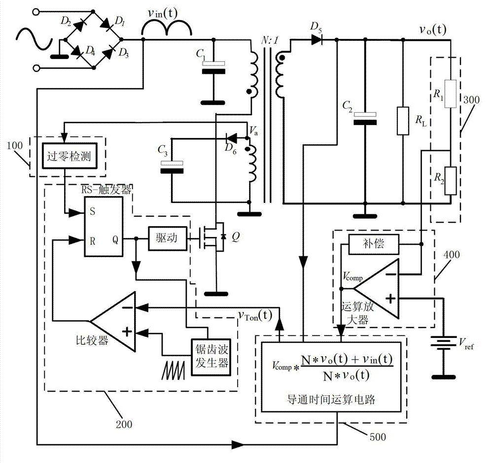
[0022] Figure 5 It shows that a specific embodiment of the present invention is a topology and control method of a critical continuous mode unity power factor flyback converter, and its specific method is:

[0023] The flyback converter control circuit includes an output voltage sampling and error amplifier circuit, a current zero-crossing detection circuit, a PWM generation circuit, an on-time calculation circuit, and a drive circuit. The negative input of the error amplifie...


PUM


Abstract

The invention discloses a control circuit and a control device for a flyback power factor corrector. The control circuit and the control device are used for controlling a flyback converter which works in a critical continuous mode to realize unit power factor; breakover time of a flyback converter circuit which works in the critical continuous mode is controlled by the control circuit so that breakover time of a switch tube varies with input voltage and output voltage in a power frequency period; turn-off time of the switch tube is determined by a zero-passing moment of transformer secondary side current; and after energy of the transformer is totally released, and because a parasitic junction capacitor of the switch tube and an excitation inductor produce resonance, the switch tube is turned on by detecting a secondary side current zero-passing moment of an auxiliary winding. By the method, a power factor of the conventional flyback power factor corrector in the critical continuous mode can be improved, and the unit power factor of the flyback converter in the critical continuous mode can be acquired. The unit power factor flyback power factor corrector in the critical continuous mode is high in efficiency, and meanwhile, the unit power factor can be acquired in the whole range of the input voltage.

Description

technical field [0001] The invention relates to power control equipment, in particular to a control method and device for flyback power factor correction. Background technique [0002] In recent years, power electronics technology has developed rapidly, and power supply technology, which is an important part of the power electronics field, has gradually become a hot spot in application and research. Switching power supply has established its mainstream position in the field of power supply because of its high efficiency and high power density, but there is a fatal weakness when it is connected to the power grid through a rectifier: the power factor is low (generally only 0.45 to 0.75), Moreover, a large number of current harmonics and reactive power will be generated in the grid to pollute the grid. There are two main methods for suppressing harmonics generated by switching power supplies: one is the passive method, that is, using passive filtering or active filtering circu...

Claims


Application Information

Patent Timeline
Patent Type & Authority Applications(China)
IPC IPC(8): H02M3/335H02M1/42
CPCY02B70/126Y02B70/10
Inventor 许建平高建龙张斐阎铁生
Owner SOUTHWEST JIAOTONG UNIV
Why Eureka
Try Eureka