
Laser cleaning system for rubber module

A laser cleaning and rubber mold technology, applied in the field of laser cleaning, can solve the problems of inapplicability and laser power loss, and achieve the effects of easy operation, fast cleaning speed and convenient operation

Inactive Publication Date: 2013-01-23
NO 717 INST CHINA MARINE HEAVY IND GRP
View PDF5 Cites 37 Cited by
  • Summary
  • Abstract
  • Description
  • Claims
  • Application Information

AI Technical Summary

Problems solved by technology

Since the system uses a fiber laser, the laser power generated will not be very large, and the fiber transmission coupling will cause a large loss of laser power. It is not suitable for industrial applications that require high-power and efficient cleaning of rubber molds.

Method used


Image

  • Laser cleaning system for rubber module
  • Laser cleaning system for rubber module
  • Laser cleaning system for rubber module

Examples


Embodiment 1

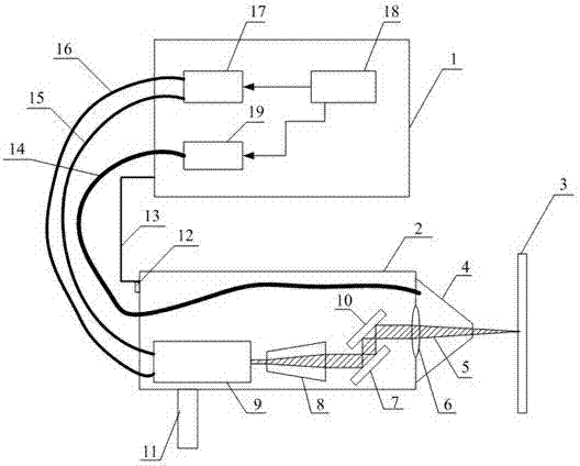
[0033] figure 1 It is a system configuration diagram of an embodiment of the present invention, which includes a laser cleaning head and a laser control system 18; the laser cleaning head includes a laser 9 and a beam expander 8, and the output light direction of the beam expander 8 is provided with a 45° total reflection mirror 7 , A scanning vibrating mirror 10 is provided on the reflected optical path of the 45° total reflection mirror 7, and a focusing lens 6 is arranged on the reflecting optical path of the scanning vibrating mirror 10, and the output end of the optical path of the focusing lens 6 outputs the laser beam 5 for cleaning the article 3.45 ° The total reflection mirror is placed at a 45° angle to the main optical path, and the scanning galvanometer is placed at a 45° angle to the main optical path. The laser cleaning head is arranged in the housing to form the cleaning processing head 2, the front end of the cleaning processing head 2 is provided with a protec...

Embodiment 2

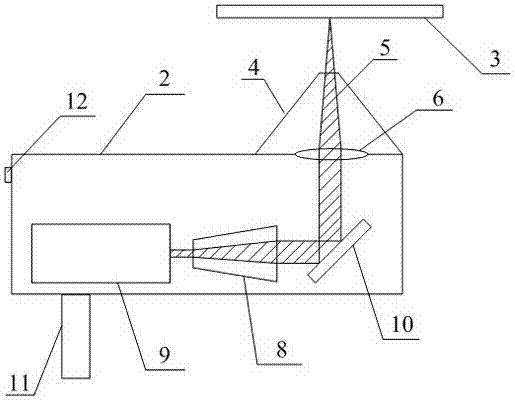
[0040] The structure and principle of the present embodiment are basically the same as the first embodiment, the difference is that the 45 ° total reflection mirror is removed in the laser cleaning head, and its structure is as follows figure 2 As shown, it includes a laser 9 and a beam expander 8 , a scanning vibrating mirror 10 is provided in the output light direction of the beam expanding mirror 8 , and a focusing lens 6 is provided on the reflected light path of the scanning vibrating mirror 10 . The scanning galvanometer 10 is placed at 45° to the main optical path to deflect the laser beam 5 by 90°. The protective cover 4 is installed on the side of the cleaning processing head 2 and is located in front of the focusing mirror 6 .


PUM


Abstract

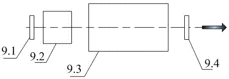
The invention provides a laser cleaning system for a rubber module, and the laser cleaning system comprises a laser cleaning head and a laser control system, wherein the laser cleaning head comprises a laser device and a beam expander, a scanning galvanometer is arranged in the output light direction of the beam expander, a focusing lens is arranged on the reflecting light path of the scanning galvanometer, and the light path output end of the focusing lens is used for cleaning articles; the laser device comprises a total reflector, an acousto-optic Q-switch, a semiconductor pumping module and an output mirror which are sequentially arranged on the light path; and the light-emitting switch of the laser device, the Q-switching drive module of the acousto-optic Q-switch, the power supply of the semiconductor pumping module, and the drive unit of the scanning galvanometer are controlled by a laser control system respectively. According to the invention, the semiconductor pumping solid pulse laser device is adopted and integrated on a cleaning machining head, the output power of laser is increased by means of acousto-optic Q-switching, and the coupling loss caused by optical fibre transmission is avoided, so that portable-type machining in a handheld mode or a manipulator clamping mode can be realized, and efficient cleaning for the rubber module can be finished.

Description

technical field [0001] The invention belongs to the technical field of laser cleaning, and in particular relates to a laser cleaning system for rubber molds, which is used for cleaning the surface of rubber molds, and can also be applied to the cleaning of dirt, rust, paint and solvent residues on the surfaces of stones, metals and other objects. cleaning. Background technique [0002] The base material of the rubber mold is usually a metal material, the most commonly used is aluminum or steel. After a certain amount of rubber products are produced by a pair of metal molds, rubber particles and dirt will adhere to the surface of the mold, resulting in rough surface of the produced rubber products and affecting product quality. , and not easy to remove from the mold. Therefore, the mold must be cleaned after a period of use. [0003] Traditional cleaning methods mainly include sandblasting, ultrasonic cleaning and dry ice cleaning. Sandblasting is time-consuming and labori...

Claims


Application Information

Patent Timeline
IPC IPC(8): B08B7/00B08B13/00B29C33/72
Inventor 朱明珠叶艾宋业英郭华福魏兴春
Owner NO 717 INST CHINA MARINE HEAVY IND GRP
Learn More