Valve control constant magnetic magnetorheological damper

A magneto-rheological damper and magneto-rheological fluid technology, applied in shock absorbers, shock absorbers, springs/shock absorbers, etc., can solve problems such as unreliability and complex structure, achieve stable performance and improve safety sex, to avoid the effect of thermogenesis

Active Publication Date: 2013-01-23
BEIJING JIAOTONG UNIV
View PDF5 Cites 19 Cited by
  • Summary
  • Abstract
  • Description
  • Claims
  • Application Information

AI Technical Summary

Problems solved by technology

[0005] In view of the problems existing in the prior art, the object of the present invention is to provide a valve that solves the unreliability of existing magneto-rheological dampers based on control power and computer control algorithms due to their complex structure. The constant magnetic magneto-rheological damper is characterized in that the valve-controlled constant magnetic magneto-rheological damper is composed of a cylinder 1, a piston 2, a piston rod 7, a bypass pipe 10 and an electro-hydraulic proportional servo valve 11, and the cylinder The cavity of body 1 is cylindrical, and the left and right ends are respectively sealed by the left end panel of the cylinder body and the right end panel of the cylinder body. The cylindrical piston 2 and the piston rod 7 are coaxial, and the piston 2 is fixed in the middle of the piston rod 7. The piston rod 7 is coaxial with the cavity of the cylinder body 1, the piston 2 is in the cavity of the cylinder body 1, and the left and right ends of the piston rod 7 protrude from the central circular hole of the left end panel of the cylinder body and the right end panel of the cylinder body r

Method used


Image

  • Valve control constant magnetic magnetorheological damper
  • Valve control constant magnetic magnetorheological damper

Examples


Embodiment Construction

[0019] The present invention will be further described below in conjunction with the embodiments and accompanying drawings.

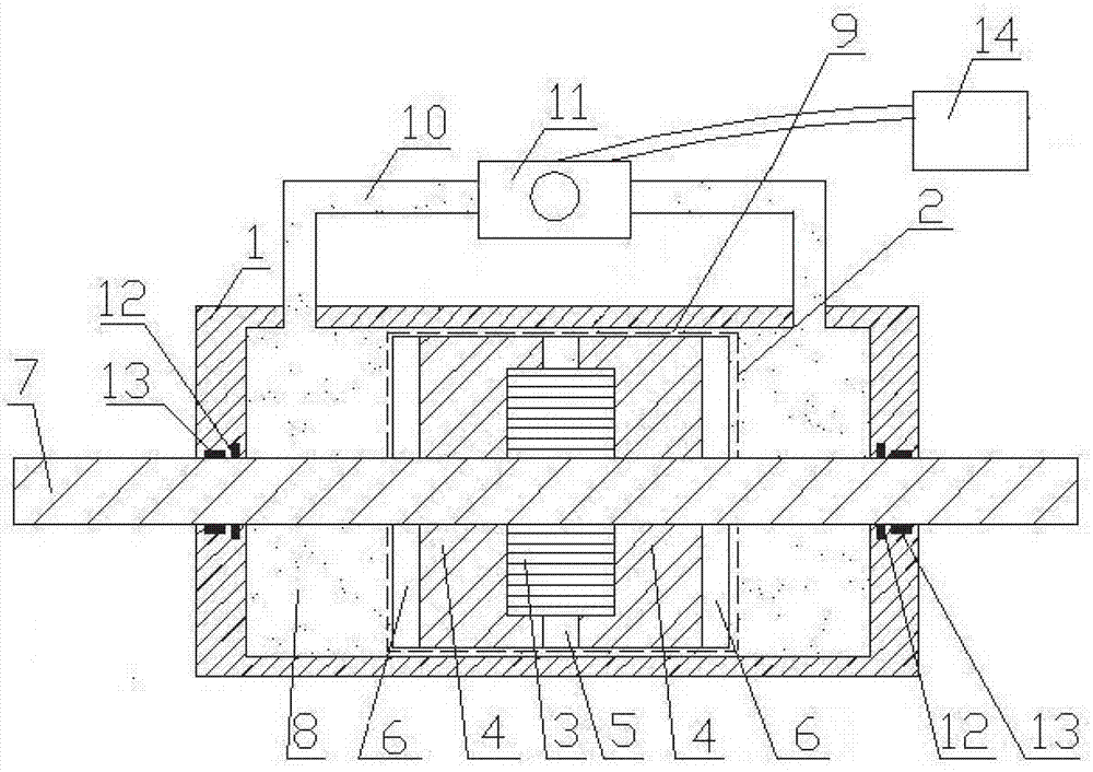
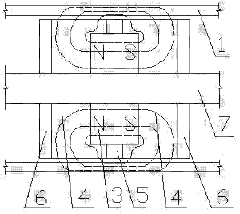
[0020] figure 1 It is a schematic structural diagram of an embodiment of a valve-controlled constant magnetic magneto-rheological damper. The valve-controlled constant magnetic magneto-rheological damper is composed of a cylinder 1, a piston 2, a piston rod 7, a bypass pipe 10 and an electro-hydraulic proportional servo valve 11. The cavity of the cylinder body 1 is cylindrical, and the left and right ends are respectively sealed by the left end panel of the cylinder body and the right end panel of the cylinder body. The cylindrical piston 2 and the piston rod 7 are coaxial, the piston 2 is fixedly connected to the middle part of the piston rod 7, the piston 2 and the piston rod 7 are coaxial with the cavity of the cylinder body 1, and the piston 2 is in the cavity of the cylinder body 1. The left and right ends of the piston rod 7 protrude from the ce...


PUM


Abstract

The invention relates to a valve control constant magnetic magnetorheological damper and belongs to the technical field of magnetorheological dampers. The valve control constant magnetic magnetorheological damper consists of a cylinder body, a piston, a piston rod, a by-pass pipe and an electric-hydraulic proportional servo valve, wherein the piston consists of an annular permanent magnet, two magnetic rings, an annular magnetic isolating body and two magnetic isolating rings; the piston is arranged in a cavity of the cylinder body; two ends of the piston rod respectively extend out of central round holes of two end face plates of the cylinder body; a magnetorheological fluid flow gap is formed between the piston and a cavity wall of the cylinder body; two ends of the by-pass pipe which is connected with in series with the electric-hydraulic proportional servo valve are respectively communicated with a left cavity and a right cavity; magnetorheological fluid is filled in the cavity of the cylinder body, the magnetorheological fluid flow gap and the by-pass pipe; and the magnetorheological fluid in the magnetorheological fluid flow gap becomes a viscous plastic body with a certain shear yield strength under the action of a constant magnetic field, and normal flow of the magnetorheological fluid is blocked. The complex control algorithm of a power supply or a computer does not need to be controlled, and the damper can work, the structure is simple, and the reliability is high.

Description

technical field [0001] The invention belongs to the technical field of magneto-rheological dampers, in particular to a valve-controlled constant magneto-rheological damper. Background technique [0002] Vibration is a common physical phenomenon. With the continuous advancement of science and technology, vibration problems in building structures, transportation, machinery and other fields have attracted people's increasing attention. In order to effectively overcome and avoid various unfavorable vibrations, domestic and foreign scholars have successively proposed passive, active and semi-active vibration control systems. Semi-active control is currently the most cost-effective and most promising control technology in the field of structural vibration control. It perfectly combines the idea of ​​active control with passive control strategies, saves control energy while implementing control, and at the same time achieves close to active control. effect, and the control process...

Claims


Application Information

Patent Timeline
IPC IPC(8): F16F9/53F16F9/32
Inventor 徐龙河戚艳红李忠献
Owner BEIJING JIAOTONG UNIV
Why Eureka
Try Eureka