Signal intensity detection circuit of trans-impedance amplifier

A technology of signal strength detection and transimpedance amplifier, applied in the direction of measuring electrical variables, measuring current/voltage, instruments, etc., can solve the problems of application environment restrictions, reduce the dynamic range and accuracy of signal strength detection, and cannot adapt to APD applications, etc., to achieve The effect of accurate detection and elimination of the influence of the average photocurrent on the DC operating point of the transimpedance amplifier

Inactive Publication Date: 2013-01-23
武汉昊昱微电子股份有限公司
View PDF5 Cites 18 Cited by
  • Summary
  • Abstract
  • Description
  • Claims
  • Application Information

AI Technical Summary

Problems solved by technology

[0003] The signal strength detection circuit of the existing transimpedance amplifier is generally sampled at the negative end of the photodiode PD, which will cause certain limitations in the application environment and cannot be adapted to APD applications
Since the input photocurrent ranges from uA level to mA level, and the range span is close to 40dBm, the traditional linear sampling method reduces the dynamic range and accuracy of signal strength detection to a certain extent.

Method used


Image

  • Signal intensity detection circuit of trans-impedance amplifier
  • Signal intensity detection circuit of trans-impedance amplifier

Examples


Embodiment

[0027] First introduce the circuit structure of the present invention:

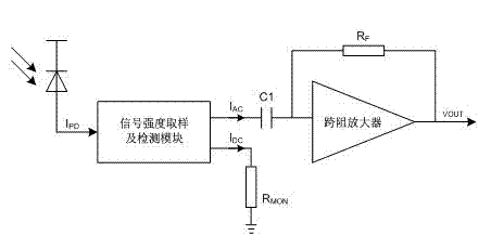
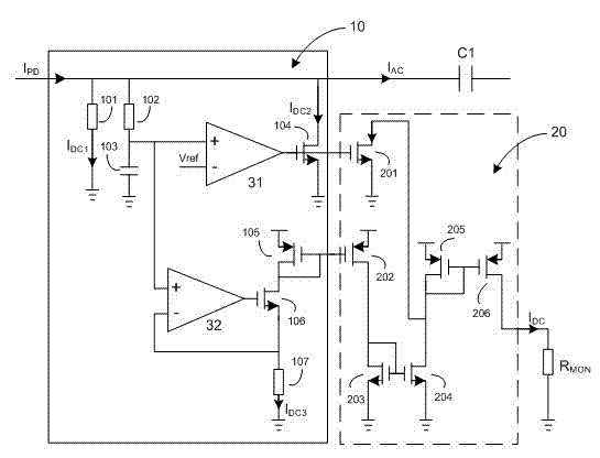
[0028] refer to figure 1 , is the application block diagram of the present invention, figure 2 It is the circuit schematic diagram of the present invention, and the present invention comprises input signal intensity sampling unit 10, to the output photocurrent I in the photodiode PD PD Sampling is carried out, and the high-frequency component and low-frequency component are separated from the sampled signal at the same time, and the high-frequency component I AC It enters the main transimpedance amplifier module through the coupling capacitor C1, and the low frequency component is sampled out of I DC2 and I DC3 two parts.

[0029] Input signal strength detection unit 20, low-frequency component sampling out I DC2 and I DC3 The two parts are the signal strength indication of the transimpedance amplifier, after R MON , converted into a voltage signal output.

[0030] On the basis of the above techn...


PUM


Abstract

The invention provides a signal intensity detection circuit of a trans-impedance amplifier. The signal intensity detection circuit obtains a sampled signal from the output photocurrent IPD (Insertion Phase Delay) of a photoelectric diode (PD), and simultaneously separates the high-frequency component and the low-frequency component of the sampled signal from each other; the high-frequency component IAC enters a main trans-impedance amplifier module through a coupling capacitor C1, while the low-frequency component IDC is the signal intensity indication of the trans-impedance amplifier; and the main trans-impedance amplifier module achieves the trans-impedance amplification function of amplifying a tiny photocurrent to a voltage signal. The signal intensity detection circuit provided by the invention directly samples the input photocurrent signal and the detection result obtained in this way is quite correct; an adaptive nonlinear sampling circuit is adopted so that the detection accuracy is improved; simultaneously, the dynamic range of the input photocurrent is very wide; and the high-frequency component is separated from the photocurrent signal and fed into the main trans-impedance amplifier module; and therefore, the influence of the low-frequency component on the direct-current working point of the main trans-impedance amplifier module in the traditional structure is avoided.

Description

technical field [0001] The invention relates to a signal strength detection circuit, in particular to a signal strength detection circuit of a transimpedance amplifier. Background technique [0002] The optical receiver is an important part of the optical fiber transmission system. Its function is to convert and amplify the attenuated weak optical pulse signal, and output it as a differential voltage signal. Transimpedance amplifiers are usually used as preamplifiers for optical receivers. [0003] The signal strength detection circuit of the existing transimpedance amplifier generally samples at the negative end of the photodiode PD, which will cause certain limitations in the application environment and cannot be adapted to the APD application. Since the input photocurrent ranges from uA level to mA level, and the change range is close to 40dBm, the traditional linear sampling method reduces the dynamic range and accuracy of signal strength detection to a certain extent. ...

Claims


Application Information

Patent Timeline
Patent Type & Authority Applications(China)
IPC IPC(8): G01R19/00
Inventor 陈卫洁詹伟程妮方海燕
Owner 武汉昊昱微电子股份有限公司
Why Eureka
Try Eureka