Manufacturing process of mobile phone built-in printed antenna

A technology of printed antennas and built-in antennas, applied in antenna supports/mounting devices, structural forms of radiation elements, etc., can solve problems such as reducing antenna gain and bandwidth, reduce antenna gain and bandwidth, reduce production costs, and improve price competition force effect

Inactive Publication Date: 2013-01-23
SHENZHEN EVERWIN PRECISION TECH
View PDF3 Cites 10 Cited by
  • Summary
  • Abstract
  • Description
  • Claims
  • Application Information

AI Technical Summary

Problems solved by technology

[0005] However, existing methods of reducing printed antennas o

Method used


Image

  • Manufacturing process of mobile phone built-in printed antenna
  • Manufacturing process of mobile phone built-in printed antenna
  • Manufacturing process of mobile phone built-in printed antenna

Examples


Embodiment 1

[0028] The manufacturing process of the mobile phone built-in printed antenna described in the application of the present invention is realized through the following technical solutions:

[0029] The process of the described built-in printed antenna comprises the following steps:

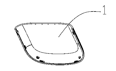
[0030] Step 1: If figure 1 As shown, the basic shape of the built-in antenna of the mobile phone is formed by injection molding. Its shape can be a separate antenna prototype, or it can be attached to the plastic shell or plastic mobile phone cover 1 of the mobile phone. The specific shape is finalized according to the actual design needs of the mobile phone;

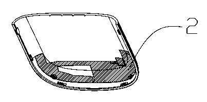
[0031] Step 2: If figure 2 As shown, the injection-molded antenna prototype is printed with a conductive ink layer 2 at a designated position on the plastic surface using a mobile printing process to prepare for the next step of electroplating copper film;

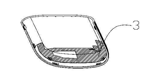
[0032] Step 3: If image 3 As shown, the printed antenna plastic prototype is el...

Embodiment 2

[0034] The process of the described built-in printed antenna comprises the following steps:

[0035] Step 1: If figure 1 As shown, the basic shape of the built-in antenna of the mobile phone is formed by injection molding. Its shape can be a separate antenna prototype, or it can be attached to the plastic shell or plastic mobile phone cover 1 of the mobile phone. The specific shape is finalized according to the actual design needs of the mobile phone;

[0036] Step 2: If figure 2 As shown, the injection-molded antenna prototype is printed with a conductive ink layer 2 at a designated position on the plastic surface using a mobile printing process to prepare for the next step of electroplating copper film;

[0037] Step 3: If image 3 As shown, the printed antenna plastic prototype is electroplated with the copper film layer 3 at the designated position on the plastic surface by electroplating process, so that it has the functions of conduction and signal reception;

[003...

Embodiment 3

[0040] Step 1: If figure 1 As shown, the basic shape of the built-in antenna of the mobile phone is formed by injection molding. Its shape can be a separate antenna prototype, or it can be attached to the plastic shell of the mobile phone or the plastic mobile phone cover 1. The specific shape is finalized according to the actual design needs of the mobile phone;

[0041] Step 2: If figure 2 As shown in the figure, the injection-molded antenna prototype is printed with a conductive ink layer 2 at a designated position on the plastic surface using a mobile printing process to prepare for the next step of electroplating copper film;

[0042] Step 3: If image 3 As shown, the printed antenna plastic prototype is electroplated with copper film layer 3 at the designated position on the plastic surface by electroplating process, so that it has the functions of conduction and signal reception;

[0043] Step 4: If Figure 5 As shown, the surface of the built-in antenna after elec...


PUM


Abstract

The invention provides a manufacturing process of a mobile phone built-in printed antenna, and the manufacturing process comprises the following steps of: carrying out injection moulding on plastic raw materials to form a basic shape of the mobile phone built-in printed antenna, printing conductive ink at an appointed position on the plastic surface of the injection moulded antenna model by using a mobile printing process so as to prepare for the next copper film electroplating, electroplating a copper film at an appointed position on the plastic surface of the printed plastic antenna model by using an electroplating process to ensure that the antenna has a conduction function and a signal reception function, and electroplating nickel on the outer surface of the mobile phone antenna electroplated with the copper film except for the external-connection conduction positions of the anode and cathode end points of the built-in antenna so as to protect the electroplated copper film layer. Moreover, gold plating can be carried out at the external-connection conduction position of the grounding end point of the built-in antenna and actually required color can be coated on the surface of the electroplated built-in antenna. According to the manufacturing process, the antenna gain and the bandwidth are not reduced, the signal strength is good and the production cost is reduced.

Description

technical field [0001] The application of the present invention relates to a manufacturing process of an antenna, especially a manufacturing process of a small-sized built-in printed antenna applied to a wireless terminal device. Background technique [0002] With the rapid development of wireless communication technology, mobile phones as wireless communication terminals are also developing towards the direction of miniaturization and diversified functions. Therefore, the size and weight of antennas (including radiators and floors), which are important components of mobile phones, also need to be reduced accordingly to meet the requirements for miniaturization of terminal equipment. [0003] At present, there are mainly two types of mobile phone antennas: built-in and external antennas. The antennas are installed as far away from the ground and buildings as possible. When the antenna is close to the reference ground, most of the energy will be concentrated between the anten...

Claims


Application Information

Patent Timeline
IPC IPC(8): H01Q1/38H01Q1/24
Inventor 刘明胜姜吉求
Owner SHENZHEN EVERWIN PRECISION TECH
Why Eureka
Try Eureka