Apparatus and method for deburring ball head by chamfering

A deburring and ball head technology, applied in the field of ball head chamfering deburring devices, can solve the problems of environmental pollution, high processing cost, unclean burr removal, etc., and achieves simple structure of the process device, reduced processing cost, and chamfering effect. good effect

Inactive Publication Date: 2013-01-30
JIANGYIN CITY TIANRUN MACHINERY
View PDF6 Cites 8 Cited by
  • Summary
  • Abstract
  • Description
  • Claims
  • Application Information

AI Technical Summary

Problems solved by technology

[0004] For machining chamfering, it is common to use a drill bit that is about twice the diameter of the hole to chamfer the hole to remove burrs. Because there is a risk of two burrs between the chamfered edge and the pre-hole, it is often not possible to remove the burr. Clean; and incapable of deburring where the chamfer drill and tool interfere
Therefore, the efficiency of chamfering and deburring by mechanical cutting is low, the labor intensity is high, and the limitations are relatively large;
[0005] Electrochemical deburring is commonly performed by electrolytic de

Method used


Image

  • Apparatus and method for deburring ball head by chamfering

Examples


Embodiment Construction

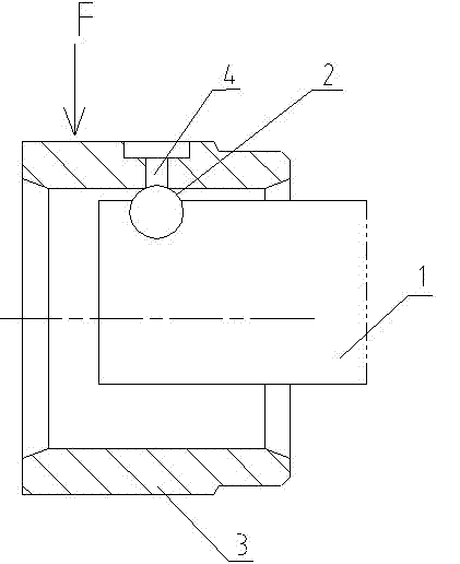
[0024] See figure 1 , The present invention relates to a ball-end chamfering and deburring device. The device includes a support 1 fixed on the worktable of a machine tool. The support 1 is provided with a cambered bump 2, preferably, A ball head is embedded on the surface of the support 1, and a part of the ball head is exposed to the support 1 to form a spherical convex convex;

[0025] The following process steps are used when chamfering:

[0026] Step 1. Put the workpiece 3 to be processed on the support 1 first;

[0027] Step 2. The arc surface of the arcuate bump 2 located in the pipe hole of the workpiece 3 is close to the hole wall of the burr hole 4. At the same time, the center of the arcuate bump 2 is located on the central axis of the burr hole 4, and the arc The diameter of the surface bump 2 is larger than the diameter of the burr hole 4;

[0028] Step 3: Apply a pressure F on the outer tube wall of the workpiece 3, so that the contact part of the burr hole 4 of the wo...


PUM


Abstract

The invention relates to an apparatus for deburring a ball head by chamfering, which comprises a supporting base (1) which is fixed on a machine tool working platform, wherein an arched convex block (2) is arranged on the supporting base (1); a ball head is embedded on the surface of the supporting base (1); and one part of the ball head is exposed out of the supporting base (1) to form a crown-shaped arched convex block. The apparatus for deburring the ball head by chamfering has the advantages of simple structure, simplicity and rapidness in processing and high processing efficiency.

Description

Technical field [0001] The invention relates to a ball head chamfering and deburring device and a method thereof, in particular to a device for chamfering a burr hole on a small-diameter workpiece and a chamfering method thereof, belonging to mechanical processing equipment and processing methods Technical field. Background technique [0002] Burr is a common defect that affects the quality and appearance of the product. In machining, burrs will be generated when processing holes, so it is necessary to use chamfering to remove burrs; [0003] There are many methods of chamfering at present, but they are mainly divided into two categories: one is to use mechanical cutting to remove material for chamfering; the other is to use electrochemical machining to remove material for chamfering; [0004] For chamfering by mechanical cutting, a drill bit about twice the diameter of the hole can be used to chamfer the hole to remove burrs. Since there is a risk of two burrs between the chamfered...

Claims


Application Information

Patent Timeline
IPC IPC(8): B23P9/02
Inventor 孙运涛徐林昌
Owner JIANGYIN CITY TIANRUN MACHINERY
Why Eureka
Try Eureka