
Fully automatic numerical control drill cutter grinding machine

A drill sharpening and fully automatic technology, which is applied to boring machine/drilling machine parts, drilling tool accessories, drilling/drilling equipment, etc. Unable to guarantee and other problems, to achieve the effects of strong rigidity, improved processing efficiency, and less consumption of grinding wheels

Active Publication Date: 2015-02-18
ZHEJIANG WEIKE MACHINERY TECH
View PDF7 Cites 0 Cited by
  • Summary
  • Abstract
  • Description
  • Claims
  • Application Information

AI Technical Summary

Problems solved by technology

[0002] At present, the processing tool industry, especially the processing of the top angle, relief angle, chisel edge, and auxiliary relief angle of the drill bit depends on several processes. Some domestic manufacturers even have a large number of manual operations. The working environment is harsh and the technical requirements for workers are relatively high. High, the processed products are unstable, the quality and output cannot be guaranteed, and the processing accuracy cannot be guaranteed by dividing several processes by the machine. The processing efficiency of expensive five-axis linkage machine tools is low and the cost is high. Generally, hydraulic machine tools can only complete one or two of them. One process, and due to the structural problems of the machine tool, the overall rigidity of the machine tool is poor, the wear of the grinding wheel is large, and the quality of the drill bit is not high

Method used


Image

  • Fully automatic numerical control drill cutter grinding machine
  • Fully automatic numerical control drill cutter grinding machine
  • Fully automatic numerical control drill cutter grinding machine

Examples


Embodiment Construction

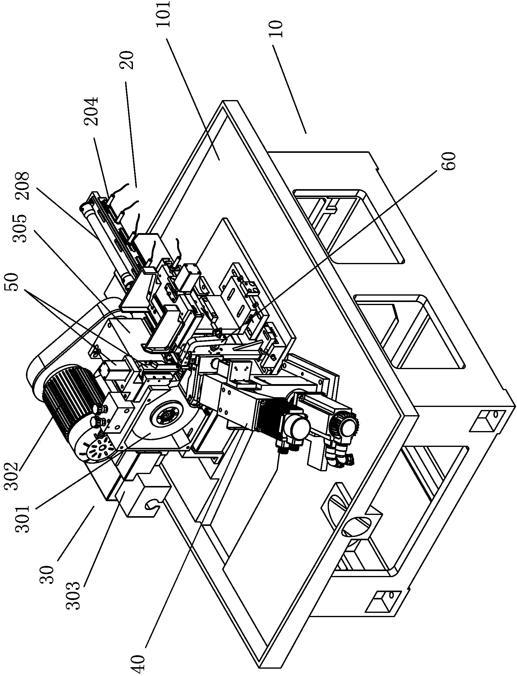
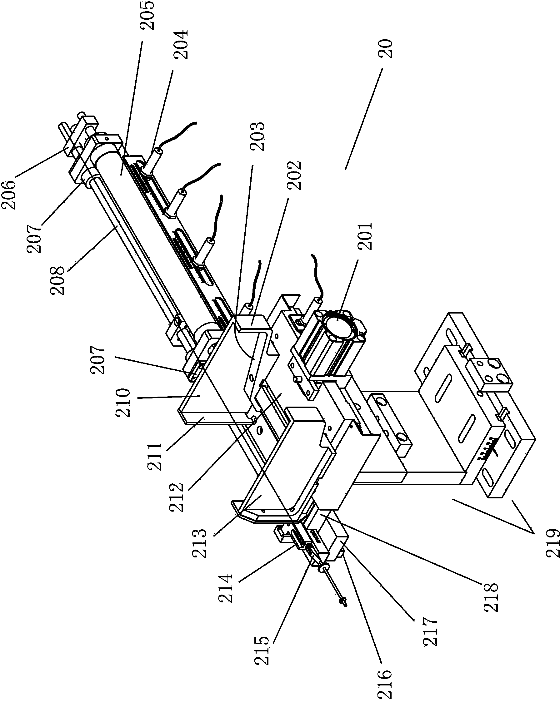
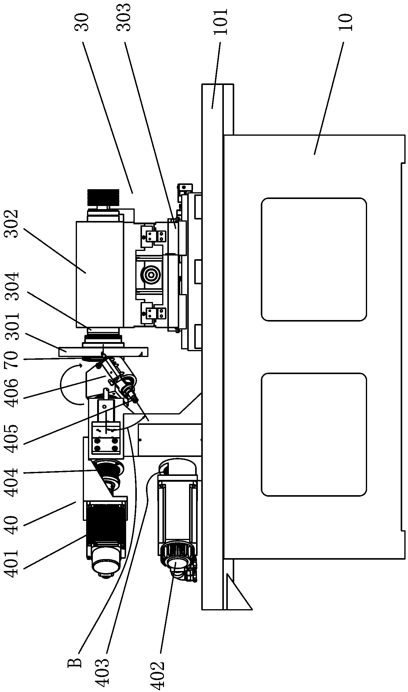
[0025] Below in conjunction with the accompanying drawings, the present invention will be further described with specific embodiments, refer to figure 1 -7:

[0026] A fully automatic CNC drill grinding machine, a grinding assembly 30 is installed on one side of the table 101 provided on the upper part of the integrally cast bed base 10, and the grinding assembly 30 includes a cross rest that is driven by a power device and can be displaced in the X and Y directions. Plate 303, a grinding head seat 305 is installed on the cross plate 303, and a high-speed grinding head spindle 304 is installed on the grinding head seat 305. The frequency conversion motor 302 of the grinding head spindle 304 rotates, the worktable on one side of the grinding wheel 301 is provided with a dual-power-driven double-shaft planetary wheel-type rotating fixture 40, and the opposite side of the rotating fixture 40 is provided with an automatic feeding device 20, on the grinding wheel 301 A grinding wh...


PUM


Abstract

The invention belongs to the technical field of grinding machines, and relates to a fully automatic numerical control drill cutter grinding machine, wherein a grinding component is arranged on the upper side of a machine base; the grinding component comprises a cross supporting plate capable of displacing in an X direction and a Y direction under the driving of a power device and a grinding wheel which is driven by a variable frequency motor; a working platform at one side of the grinding wheel is provided with a double-axle planet wheel type rotary clamp driven by two powers; an automatic feeding device is arranged on the opposite side of the rotary clamp; the cross supporting plate at the upper side of the grinding wheel is provided with a grinding wheel trimming device; a cooling conduct of a cooling system which is arranged on the machine base is led to a nozzle on the grinding part; a drilling bit locating device is arranged between the automatic feeding device and the rotary clamp; and actions of the cross supporting plate, the variable frequency motor, the rotary clamp, the automatic feeding device, the drilling bit locating device and the grinding wheel trimming device are controlled by a controller. The fully automatic numerical control drill cutter grinding machine has the advantages that: a fully automatic processing on the drilling bit is realized after loading, and the purpose of operating on multiple machines by one person is implemented; the fully automatic numerical control drill cutter grinding machine is high in efficiency, good in fineness and low in labor intensity, and the machine doubles the efficiency in comparison with the conventional hydraulic equipment.

Description

technical field [0001] The invention belongs to the technical field of grinding machines, in particular to a fully automatic numerical control drill bit grinding machine. Background technique [0002] At present, in the machining tool industry, especially the machining of the top angle, relief angle, chisel edge and auxiliary relief angle of the drill bit depends on several processes. Some domestic manufacturers even have a large number of manual operations. The working environment is harsh, and the technical requirements for workers are relatively high. High, the processed products are unstable, and the quality and output cannot be guaranteed. The machining accuracy cannot be guaranteed by using the machine in several processes. The processing efficiency of the expensive five-axis linkage machine tool is low and the cost is high. Generally, hydraulic machine tools can only complete one or two of them. Due to the structural problems of the machine tool, the overall rigidity ...

Claims


Application Information

Patent Timeline
Patent Type & Authority Patents(China)
IPC IPC(8): B24B3/24
CPCY02P70/10
Inventor 王宏波
Owner ZHEJIANG WEIKE MACHINERY TECH
Learn More