Premixed spray quenching system for steel rail
A technology of spray cooling and quenching system, applied in quenching device, track, track maintenance and other directions, can solve the problems of high energy consumption, high processing cost, high noise, etc., to ensure the quality of quenching, low processing cost and low energy consumption. Effect
- Summary
- Abstract
- Description
- Claims
- Application Information
AI Technical Summary
Problems solved by technology
Method used
Image
Examples
Embodiment 1
[0023] The spray cooling and quenching system of the premixed rail is an improvement on the spray cooling and quenching equipment.
[0024] The original blast cooling and quenching equipment directly sprays compressed air from the air inlet pipe 2 through the air outlet 3 at the end of the air inlet pipe 2 to cool the steel rails. There are six air outlets 3 of the original air jet cooling and quenching equipment, which are respectively located above the rail head tread 5 , on both sides of the rail head 4 , on both sides of the rail waist 6 and below the rail bottom 7 .
[0025] Its improvement method is to set several groups of atomizing and humidifying nozzles 1 on the air inlet pipe 2 of the jet cooling and quenching equipment.
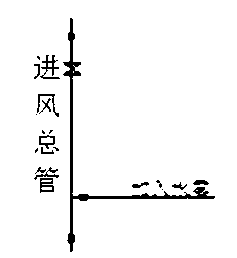
[0026] Such as figure 1 As shown, the air inlet pipe 2 selects the main air inlet pipe, and the atomizing and humidifying nozzle 1 is a single-medium centrifugal atomizing nozzle. The air main is connected and sealed.
[0027] The atomized wate...
Embodiment 2
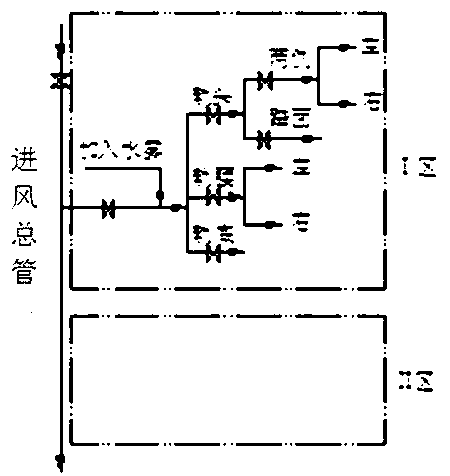
[0029] The structure of this embodiment is basically the same as that of Embodiment 1, the difference is that the air inlet duct 2 selects the air inlet branch pipe, and the number of atomizing and humidifying nozzles 1 is in groups.
[0030] Such as figure 2 As shown, the atomizing and humidifying nozzle 1 is a single-medium centrifugal atomizing nozzle, and four atomizing and humidifying nozzles 1 are gathered at one point to form a group, and are connected and sealed with the air inlet branch pipe through bolts and flanges.
[0031] The atomized water mist is sprayed into the air inlet branch pipe from the atomization humidification nozzle 1 through the pipeline, and after mixing with the compressed air in the air inlet branch pipe, the air outlet 3 connected to the air inlet branch pipe at each place will spray the air containing the water mist. Compressed air is blown onto the rails.
Embodiment 3
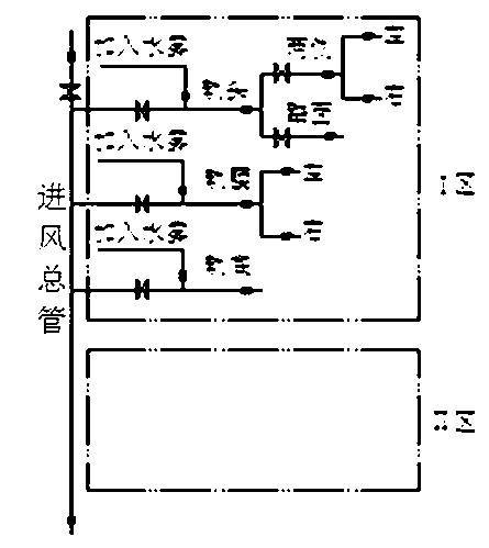
[0033] The structure of this embodiment is basically the same as that of Embodiment 1, the difference is that the air inlet duct 2 selects the air inlet branch pipe, and the number of atomizing and humidifying nozzles 1 is three groups.
[0034] Such as image 3 As shown, the positions of the three groups of atomizing and humidifying nozzles 1 are respectively at the air inlet branch pipe at the rail head 4, the air inlet branch pipe at the rail waist 6, and the air inlet branch pipe at the rail bottom 7.
[0035] Such as Figure 4 As shown in the figure, atomizing and humidifying nozzle 1 is a single-medium centrifugal atomizing nozzle, which is concentrated at one point to form a group, and is connected and sealed with the air inlet branch pipe through bolts and flanges. The air inlet branch pipe is connected and sealed.
[0036] The atomized water mist is sprayed into the three air inlet branch pipes from the atomization humidification nozzle 1 through the pipeline, and a...
PUM
 Abstract
Description
Claims
Application Information
 - R&D
- Intellectual Property
- Life Sciences
- Materials
- Tech Scout
- Unparalleled Data Quality
- Higher Quality Content
- 60% Fewer Hallucinations
Browse by: Latest US Patents, China's latest patents, Technical Efficacy Thesaurus, Application Domain, Technology Topic, Popular Technical Reports.
© 2025 PatSnap. All rights reserved.Legal|Privacy policy|Modern Slavery Act Transparency Statement|Sitemap|About US| Contact US: help@patsnap.com


