Hydraulic superhigh-frequency vibrating power head

A power head, ultra-high frequency technology, applied in drilling equipment, drilling equipment and methods, impact drilling and other directions, can solve the problems of shallow drilling depth, low vibration frequency, poor formation adaptability, etc. Synchronized operation, improve work efficiency, increase drilling speed and sampling depth effect

Inactive Publication Date: 2013-01-30
中煤地第二勘探局集团有限责任公司 +1
View PDF5 Cites 22 Cited by
  • Summary
  • Abstract
  • Description
  • Claims
  • Application Information

AI Technical Summary

Problems solved by technology

[0004] In order to overcome the shortcomings of the existing vibratory drilling rigs, such as low vibration frequency, shallow drilling depth, and poor formation adaptability, the purpose of the present invention is to provide a hydraulic ultra

Method used


Image

  • Hydraulic superhigh-frequency vibrating power head
  • Hydraulic superhigh-frequency vibrating power head
  • Hydraulic superhigh-frequency vibrating power head

Examples


Embodiment 1

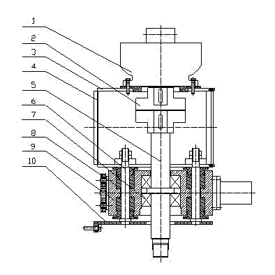
[0017] figure 1 Schematically shows the structure of the preferred embodiment of the present invention, as shown in the figure, this preferred embodiment includes a rotary motor 1, a coupling 2, a coupling box 3, a power head back plate 4, a main shaft 5, a vibration Vibrator 9, vibration damping device and supporting plate 10, rotary motor 1 is connected with the upper end of the main shaft 5 through the coupling 2, the main shaft runs through the vibrator 9 up and down, and the lower end of the main shaft 5 is connected with the drill pipe and the drilling tool (not shown in the figure) . The vibrator 9 is connected with the base plate of the shaft coupling box 3 through a damping device, and the power head back plate 4 is connected to the chain back plate of the rig mast, and can slide up and down on the rig mast to achieve the purpose of drilling and lifting the drill. The supporting plate 10 plays a safety role, preventing the vibrator from falling suddenly and causing ...

Embodiment 2

[0020] In embodiment 2, other structures are all identical with embodiment 1 structure, and difference is:

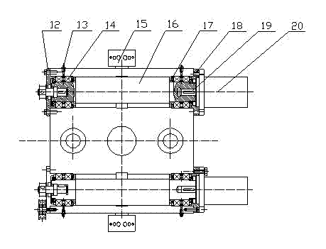
[0021] The synchronous belt / synchronous wheel forced synchronization mechanism is placed on the side close to the power head back plate 4, including the synchronous wheel 21, the guide wheel 24, the pressing wheel 23 and the synchronous belt 22, and the synchronous belt / synchronous wheel forced synchronous mechanism can ensure two The rotational speeds of the eccentric shaft 16 are completely synchronized to better realize self-synchronous operation.

Embodiment 3

[0023] In Embodiment 3, other structures are the same as those in Embodiment 2, except that the high-speed bearing cooling and lubricating mechanism includes an oil cup 13 , an air filter 15 and an air suction impeller 17 . Grease is injected through the oil cup 13 to lubricate the high-speed bearing 14 , and the eccentric shaft 16 drives the suction impeller 17 to rotate at a high speed to inhale air to air-cool the high-speed bearing 14 .


PUM


Abstract

The invention discloses a hydraulic superhigh-frequency vibrating power head and belongs to the field of shallow drilling and sampling. The hydraulic superhigh-frequency vibrating power head comprises a rotary motor, a coupler, a coupler box, a vibrator, a vibration damper, a spindle, a power head back plate and a support plate, wherein the rotary motor is connected with the upper end of the spindle via the coupler, and the spindle is vertically penetratingly arranged in the vibrator. The vibrator is connected with a bottom plate of the coupler box via the vibration damper and comprises a vibrator box, two groups of high-speed hydraulic motors, two eccentric shafts, a synchronous belt/ synchronous wheel forced synchronizing mechanism and a high-speed bearing cooling and lubricating device, wherein the two groups of high-speed hydraulic motors are symmetrically arranged on two sides of the spindle, the high-speed hydraulic motors drive the eccentric shafts to rotate via key joint, and the two eccentric shafts can realize synchronous running via the synchronous belt/ synchronous wheel forced synchronizing mechanism. The hydraulic superhigh-frequency vibrating power head is capable of conveniently and effectively realizing shallow drilling and sampling on various overburden layers, drilling speed is improved, and popularization is facilitated.

Description

technical field [0001] The invention relates to a hydraulic ultra-high-frequency vibration power head, in particular to a hydraulic ultra-high-frequency vibration power head for a shallow drilling sampling rig. Background technique [0002] At present, a large number of shallow drilling samples are required in oil and gas, resource exploration and infrastructure construction. Shallow drilling sampling basically adopts geological core drilling rigs mainly for rotary drilling. Flushing fluid (mud, air or foam) is required to flush the borehole, and the water in the mud can easily enter the sample, contaminate the sample, and cause the test result of the sample to be distorted. At the same time, air drilling brings a lot of dust pollution, which is not good for the health of operators and the environment. In addition, rotary drilling cannot be used in arid areas in the west and areas where many water sources are difficult to enter (such as tailings dams), and vibration drillin...

Claims


Application Information

Patent Timeline
IPC IPC(8): E21B1/26
Inventor 刘勤学刘宝林赵晓冬李国民陆卫星周琴胡远彪王瑜张蔚吴浩任晓飞
Owner 中煤地第二勘探局集团有限责任公司
Why Eureka
Try Eureka