Heat control system and heat control method of engine of milling machine

An engine and thermal control technology, applied in the direction of machine/engine, engine components, engine cooling, etc., can solve the problems of low heat utilization rate and high fuel consumption of the engine system, and achieve the effect of reducing fuel consumption and improving thermal efficiency.

Inactive Publication Date: 2013-01-30
CHENGDU XINZHU ROAD & BRIDGE MASCH CO LTD
View PDF6 Cites 4 Cited by
  • Summary
  • Abstract
  • Description
  • Claims
  • Application Information

AI Technical Summary

Problems solved by technology

Neither of the two methods can control the heat from the temperature, resulting in low heat utilization rate of the engine system and high fuel consumption

Method used


Image

  • Heat control system and heat control method of engine of milling machine
  • Heat control system and heat control method of engine of milling machine

Examples


Embodiment Construction

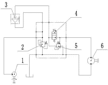
[0015] A milling machine engine thermal control system, such as figure 1 As shown, the hydraulic components include: pump 1, relief valve 2, filter 3, electric proportional throttle valve 4, differential pressure sensitive valve 5 and so on. The hydraulic oil output by the pump 1 under the driving of the engine passes through the filter 3 to the electric proportional throttle valve 4, and the outlet of the electric proportional throttle valve is connected to the motor 6, and the cooling fan is driven by the motor. There is an overflow valve 2 in front of the filter 3 to protect the system. When the pressure difference between the inlet and outlet of the electric proportional throttle valve 4 is greater than the set pressure of the differential pressure sensitive valve 5, the oil returns to the oil tank through the differential pressure sensitive valve 5 to reduce the pressure loss. The rotational speed of the fan is controlled electrically to adjust the magnitude of the input...


PUM


Abstract

The invention discloses a heat control system and a heat control method of an engine of a milling machine. The heat control system comprises a microcontroller, wherein the microcontroller is respectively connected with a coolant temperature sensor arranged in engine coolant, an air inlet temperature sensor arranged at an engine air inlet and a hydraulic oil temperature sensor arranged in engine hydraulic oil through a signal line; and the microcontroller is further connected with an electric proportion throttle valve through a signal line. The heat control system has the advantages that the temperature of an engine system is monitored in real time through a temperature sensor, a temperature value is set up and fed back to the controller, and furthermore the set temperature is compared with the actual temperature through the controller so as to control the electric proportion throttle valve of a fan, so that the motor of the fan is adjusted, the rotation speed of the fan is changed, and ultimately the heat balance of the engine of the milling machine is realized; the heat efficiency of the engine of the milling machine and a hydraulic system are effectively improved, the fuel consumption is reduced, thus enabling the system to achieve an optimal working state.

Description

technical field [0001] The invention belongs to the technical field of road surface maintenance machinery and equipment, and in particular relates to an engine thermal control system and a control method of a milling machine. Background technique [0002] The milling machine is a special equipment used for road maintenance and road reconstruction. Its working principle is that the continuous rotary motion of the working device cuts off a certain depth of road material, and the continuous walking of the equipment walking mechanism makes the cutting process along the walking direction. It is carried out continuously, and the waste is continuously transported to the waste car through the conveying device, so as to achieve the purpose of continuous cutting of the road surface. Engine thermal control is the main factor affecting the power system of the milling machine. [0003] At present, there are two main types of engine thermal control for most models of milling machines at ...

Claims


Application Information

Patent Timeline
Patent Type & Authority Applications(China)
IPC IPC(8): F01P7/04F01P11/16F01P11/14
Inventor 梁云龙黄兵张诚实陈波
Owner CHENGDU XINZHU ROAD & BRIDGE MASCH CO LTD
Why Eureka
Try Eureka