Angular displacement optical fiber gyroscope

A fiber optic gyroscope and angular displacement technology, which is applied in the field of gyroscopes, can solve problems such as complex signal processing of fiber optic gyroscopes, and achieve the effects of low cost, simple method, and cost saving

Active Publication Date: 2013-01-30
CHONGQING HUAYU ELECTRIC GRP
View PDF7 Cites 7 Cited by
  • Summary
  • Abstract
  • Description
  • Claims
  • Application Information

AI Technical Summary

Problems solved by technology

[0009] Aiming at the above-mentioned deficiencies in the prior art, the present invention aims to provide a new type of fiber optic gyroscope with angular displacement output function to solve the pr...

Method used


Image

  • Angular displacement optical fiber gyroscope
  • Angular displacement optical fiber gyroscope
  • Angular displacement optical fiber gyroscope

Examples


Embodiment Construction

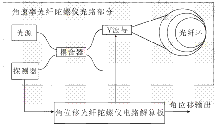
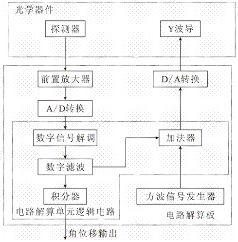
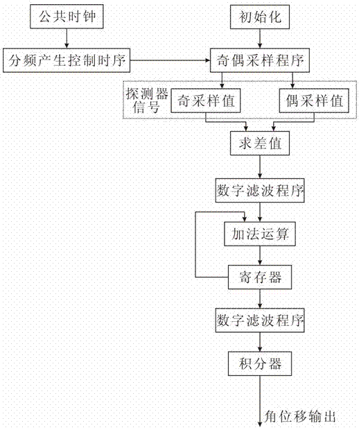
[0031] Such as figure 1 , figure 2 As shown, an angular displacement fiber optic gyroscope includes an optical path part and a circuit part; the optical path part is composed of an optical fiber ring, a Y waveguide, a coupler, a light source and a detector. In the optical path part, an optical signal passes through a Sagnac The effect produces a phase shift, and the phase shift signal is parasitic in the interference light intensity and is converted and output by the detector as a detector signal (electrical signal); in the circuit part, the detector signal output by the detector passes through the preamplifier and the analog-to-digital conversion circuit Carry out signal amplification and conversion, it is characterized in that: the circuit part also includes circuit solving unit logic circuit, the circuit solving unit logic circuit carries out digital signal demodulation, digital filtering and integral processing to above-mentioned amplified, converted detector signal , so...


PUM


Abstract

The invention discloses an angular displacement optical fiber gyroscope, which comprises an optical path part and a circuit part. The optical path part consists of an optical fiber ring, a Y waveguide, a coupler, an optical source and a detector; in the optical path part, an optical signal generates phase shifting through a Sagnac effect; the phase-shifting signal parasitizes in interference optical intensity and is converted and output as a detector signal (electric signal) by the detector; in the circuit part, the detector signal output by the detector is subjected to signal amplification and conversion through a preliminary amplifier and an analog-to-digital conversion circuit; and the circuit part also comprises a circuit resolving unit logic circuit; the circuit resolving unit logic circuit resolves the rotation angle information of the optical fiber gyroscope through carrying out digital signal demodulation, digital filtering and integral treatment on the amplified and converted detector signal, judges and outputs an angle direction. The angular displacement optical fiber gyroscope has the advantages that a program, logic and the like for processing the signal in the circuit part are innovated and improved, so that the optical fiber gyroscope has an angular displacement output function.

Description

technical field [0001] The invention belongs to the technical field of gyroscopes, in particular to optical fiber gyroscopes used for high-speed rail track detection or other optical fiber gyroscopes that require angular displacement output. [0002] Background technique [0003] The fiber optic gyroscope is a sensitive element based on the optical fiber coil. The light emitted by the laser diode propagates along the optical fiber in two directions. The change of the light propagation path determines the angular displacement of the sensitive element. Compared with traditional mechanical gyroscopes, fiber optic gyroscopes have the advantages of all solid state, no rotating parts and friction parts, long life, large dynamic range, instant start, simple structure, small size, light weight, etc.; compared with laser gyroscopes , The fiber optic gyroscope has no locking problem, and does not need to precisely process the optical path in the quartz block, and the cost is low. ...

Claims


Application Information

Patent Timeline
IPC IPC(8): G01C19/72
Inventor 刘平陈斌李光辉王树春顾云飞
Owner CHONGQING HUAYU ELECTRIC GRP
Why Eureka
Try Eureka