Grid-connected inverter and control method thereof

An inverter and inverter unit technology, applied in the field of circuits, can solve the problems of high switching cost and large loss, and achieve the effect of eliminating switching elements, reducing heat loss, and reducing the cost of the whole machine

Active Publication Date: 2013-01-30
SHENZHEN HOPEWIND ELECTRIC CO LTD
View PDF7 Cites 14 Cited by
  • Summary
  • Abstract
  • Description
  • Claims
  • Application Information

AI Technical Summary

Problems solved by technology

[0004] The technical problem to be solved by the present invention is to provide an on-off control for the filter capacitor series switching elements in the filter unit in view of the defect that the existing grid-connected inverter realizes the line on-off through the contactor, which leads to high switching costs and large losses. grid-connected inverter and its control method

Method used


Image

  • Grid-connected inverter and control method thereof
  • Grid-connected inverter and control method thereof
  • Grid-connected inverter and control method thereof

Examples


Embodiment Construction

[0031] In order to make the object, technical solution and advantages of the present invention clearer, the present invention will be further described in detail below in conjunction with the accompanying drawings and embodiments.

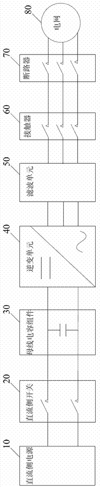
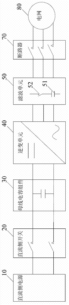
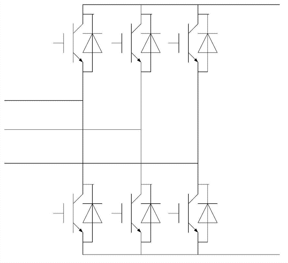
[0032] see figure 2 , is a main circuit topology diagram of a preferred embodiment of the grid-connected inverter according to the present invention. like figure 2 As shown, the grid-connected inverter provided by the present invention includes a main control unit (not shown in the figure), and a DC-side power supply 10, a DC-side switch 20, a bus capacitor assembly 30, an inverter unit 40, and a filter unit connected in sequence 50 and circuit breaker 70. Among them, the DC side power supply 10 is output to the bus capacitor assembly 30 through the DC side switch 20, and then through the inverter unit 40 for AC inversion, a sinusoidal voltage is obtained through the filter unit 50, the circuit breaker 70 is closed, and the output is output to ...


PUM


Abstract

The invention relates to a grid-connected inverter and a control method thereof. The grid-connected inverter comprises a master control unit as well as a DC-side power supply, a DC-side switch, a busbar capacitor assembly, an inverter unit, a filter unit and a circuit breaker which are connected in sequence; the filter unit at least comprises a filter capacitor and a switch element connected with the filter capacitor in series; when the detected DC voltage reaches startup voltage, the master control unit sends a PWM (Pulse Width Modulation) wave to start the inverter unit to power on the switch element, and when the output voltage of the filter unit reaches the power grid voltage, the master control unit controls the circuit breaker to be powered on; and the master control unit also controls the inverter unit to stop inversion and power off the switch element when the detected DC voltage is lower than the startup voltage. According to the invention, because the switch element is additionally arranged on a branch of the filter capacitor of the filter unit, the grid-connected inverter is freely controlled not to absorb reactive power from a power grid under the circuit breaker is not powered off, so that the breaking frequency of the circuit breaker is reduced, the system efficiency is improved and the complete machine cost is reduced.

Description

technical field [0001] The present invention relates to the technical field of circuits, and more specifically, to a grid-connected inverter and a control method thereof. Background technique [0002] like figure 1 Shown is the topological structure diagram of the main circuit of the existing grid-connected inverter. The existing grid-connected inverter mainly includes a DC side power supply 10, a DC side switch 20, a bus capacitor assembly 30, an inverter unit 40, a filter unit 50, a contactor 60, a circuit breaker 70 and a main control unit (not shown) . Among them, the DC-side power supply 10 outputs to the bus capacitor assembly 30 through the DC-side switch 20, and then performs AC inversion through the inverter unit 40, and obtains a sinusoidal voltage through the filter unit 50, the contactor 60 is closed, and the output passes through the circuit breaker 70 to Grid 80. The filtering unit 50 is a commonly used LC filter circuit or LCL filter circuit. The working ...

Claims


Application Information

Patent Timeline
Patent Type & Authority Applications(China)
IPC IPC(8): H02J3/42H02M7/48H02M1/12
Inventor 曾建友
Owner SHENZHEN HOPEWIND ELECTRIC CO LTD
Why Eureka
Try Eureka