Internal combustion engine and control device for internal combustion engine
A technology of a control device and an internal combustion engine, applied in engine control, internal combustion piston engine, electrical control, etc., can solve problems such as fuel utilization deterioration, and achieve the effects of suppressing deflagration, increasing EGR rate, and ensuring heat dissipation performance.
- Summary
- Abstract
- Description
- Claims
- Application Information
AI Technical Summary
Problems solved by technology
Method used
Image
Examples
Embodiment approach 1
[0054] [Structure of Embodiment 1]
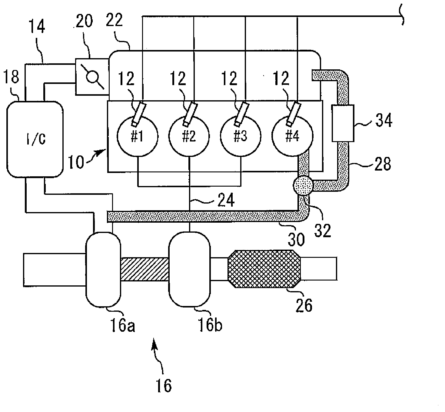
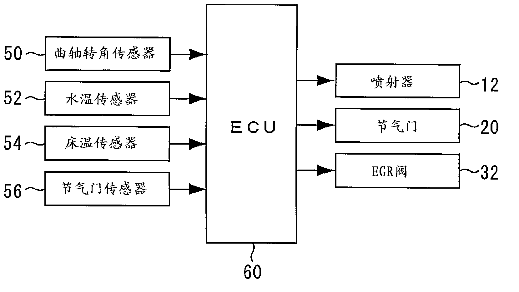
[0055] First, refer to Figure 1 to Figure 10 , Embodiment 1 of the present invention will be described. figure 1 It is a figure for demonstrating the system structure of Embodiment 1 of this invention. The system of the present embodiment includes an engine 10 as an internal combustion engine. The engine 10 is an in-line four-cylinder engine, and its ignition sequence is first→third→fourth→second cylinders. Each cylinder of the engine 10 is provided with an injector 12 for directly injecting fuel into the cylinder. Further, each cylinder of the engine 10 is provided with an ignition plug (not shown) for igniting the air-fuel mixture in the cylinder.
[0056] A compressor 16 a of a turbocharger 16 is provided in an intake passage 14 of the engine 10 . The turbocharger 16 includes a turbine 16b integrally connected to a compressor 16a. The turbine 16b is provided in an exhaust passage 24 to be described later, and the compressor 16a is...
Embodiment approach 2
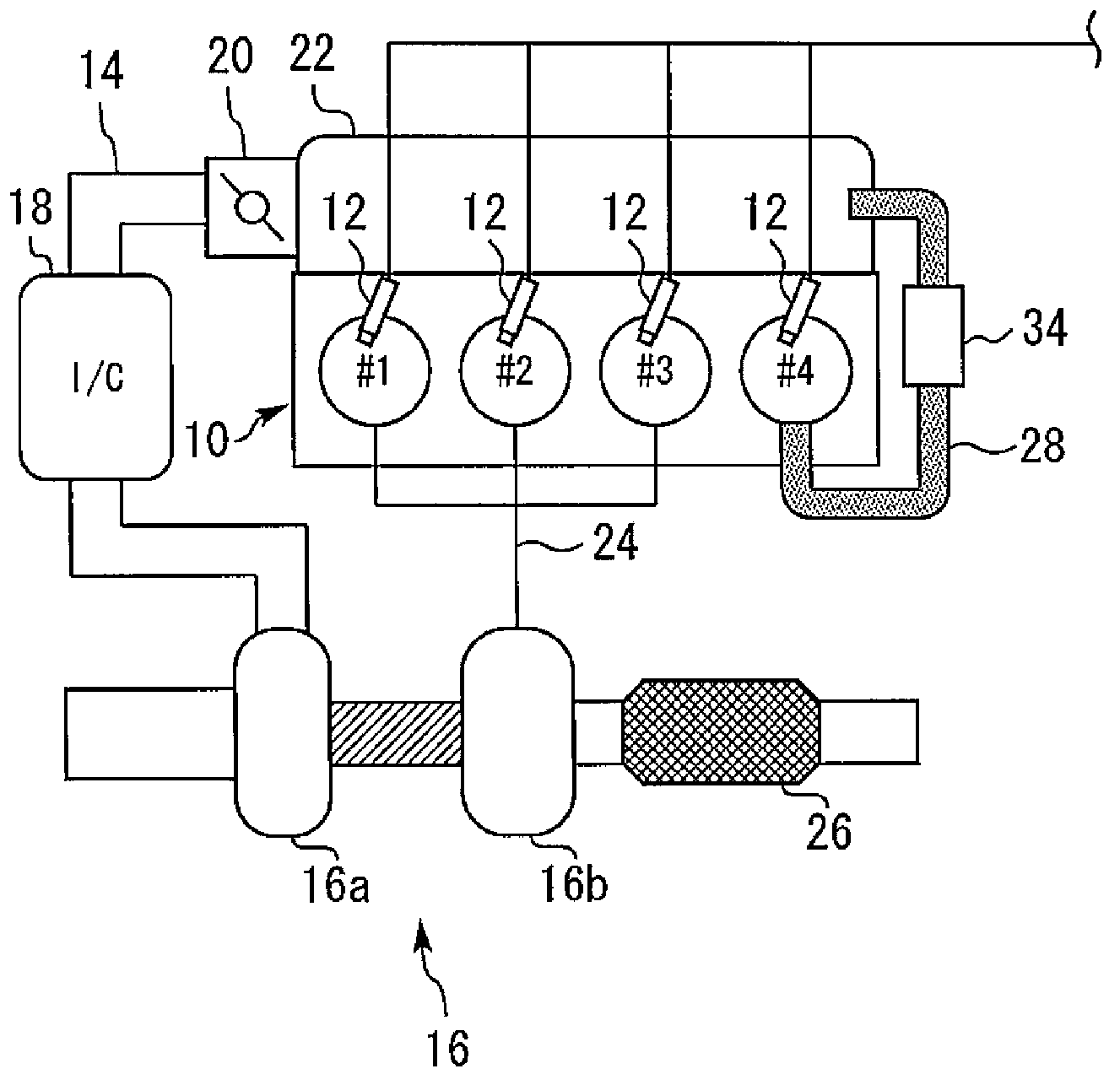
[0095] Second, refer to Figure 11 ~ Figure 13 Embodiment 2 of the present invention will be described. Regarding this embodiment, the description will focus on the differences from the first embodiment described above, and the description of the same items will be simplified or omitted.
[0096] [Structure of Embodiment 2]
[0097] Figure 11 It is a figure for demonstrating the system structure of Embodiment 2. The system of the present embodiment is different from the system configuration of the first embodiment in that an EGR catalyst 36 for purifying EGR gas is provided in the EGR passage 28 .
[0098] [Features of Embodiment 2]
[0099] In Embodiment 1, when the operating range of the engine 10 is in the high load range, the opening degree of the EGR valve 32 is adjusted to control the flow of EGR gas to the route b side. However, even if the control of Embodiment 1 is executed, when the actual engine cooling water temperature Tw becomes high, the heat dissipation p...
Embodiment approach 3
[0112] Second, refer to Figure 14 ~ Figure 16 Embodiment 3 of the present invention will be described. The present embodiment is characterized in that, in addition to the system configuration of the above-mentioned second embodiment, the ECU 60 executes the Figure 16 program of.
[0113] [Feature of Embodiment 3]
[0114] In Embodiment 2, when the ECU 60 determines that the current operating range of the engine 10 is in the high load range, the opening degree of the EGR valve 32 is adjusted so that the EGR gas flows to both the paths a and b (see Figure 12 step 112). However, it takes a certain period of time until the opening of the EGR valve 32 converges to the target opening (hereinafter referred to as "convergence delay period t"). EGR ”). Therefore, there exists a period of convergence delay t EGR The case where the engine cooling water temperature Tw and the bed temperature Tc rise. On the other hand, when transitioning to the high load range in a short period o...
PUM
 Abstract
Description
Claims
Application Information
 - R&D
- Intellectual Property
- Life Sciences
- Materials
- Tech Scout
- Unparalleled Data Quality
- Higher Quality Content
- 60% Fewer Hallucinations
Browse by: Latest US Patents, China's latest patents, Technical Efficacy Thesaurus, Application Domain, Technology Topic, Popular Technical Reports.
© 2025 PatSnap. All rights reserved.Legal|Privacy policy|Modern Slavery Act Transparency Statement|Sitemap|About US| Contact US: help@patsnap.com


