Coaxial bidirectional winding accelerated shipboard aircraft catapult

A carrier-based aircraft and catapult technology, applied in the direction of launching/dragging transmission devices, etc., can solve problems such as unreliable stability, high power consumption, and complex structure, and achieve fast overload response adaptation, less space occupation, and simple structure Effect

Inactive Publication Date: 2013-02-06
朱惠芬
View PDF7 Cites 6 Cited by
  • Summary
  • Abstract
  • Description
  • Claims
  • Application Information

AI Technical Summary

Problems solved by technology

[0004] The second is the ski-jump flight deck on the Russian aircraft carrier, that is, the aircraft accelerates on the deck by itself and passes an upwardly tilted runway to realize the ski-jump flight from the ship. The disadvantage of the ski-jump ejection method is that the deck must be built The ski-jump take-off platform must use a twin-engine aircraft with a large thrust-to-weight ratio. Single-engine fighters cannot be used, so the types of carrier-based aircraft are restricted
[0005] The third type of electromagnetic carrier-based aircraft catapult, the United States has successfully trial-produced it. It took more than 20 years and cost 2.6 billion. However, due to its large size, huge power consumption, overly complicated structure, and very unreliable stability, the US military has not dared to launch it yet. equip aircraft carrier

Method used


Image

  • Coaxial bidirectional winding accelerated shipboard aircraft catapult
  • Coaxial bidirectional winding accelerated shipboard aircraft catapult
  • Coaxial bidirectional winding accelerated shipboard aircraft catapult

Examples


Embodiment

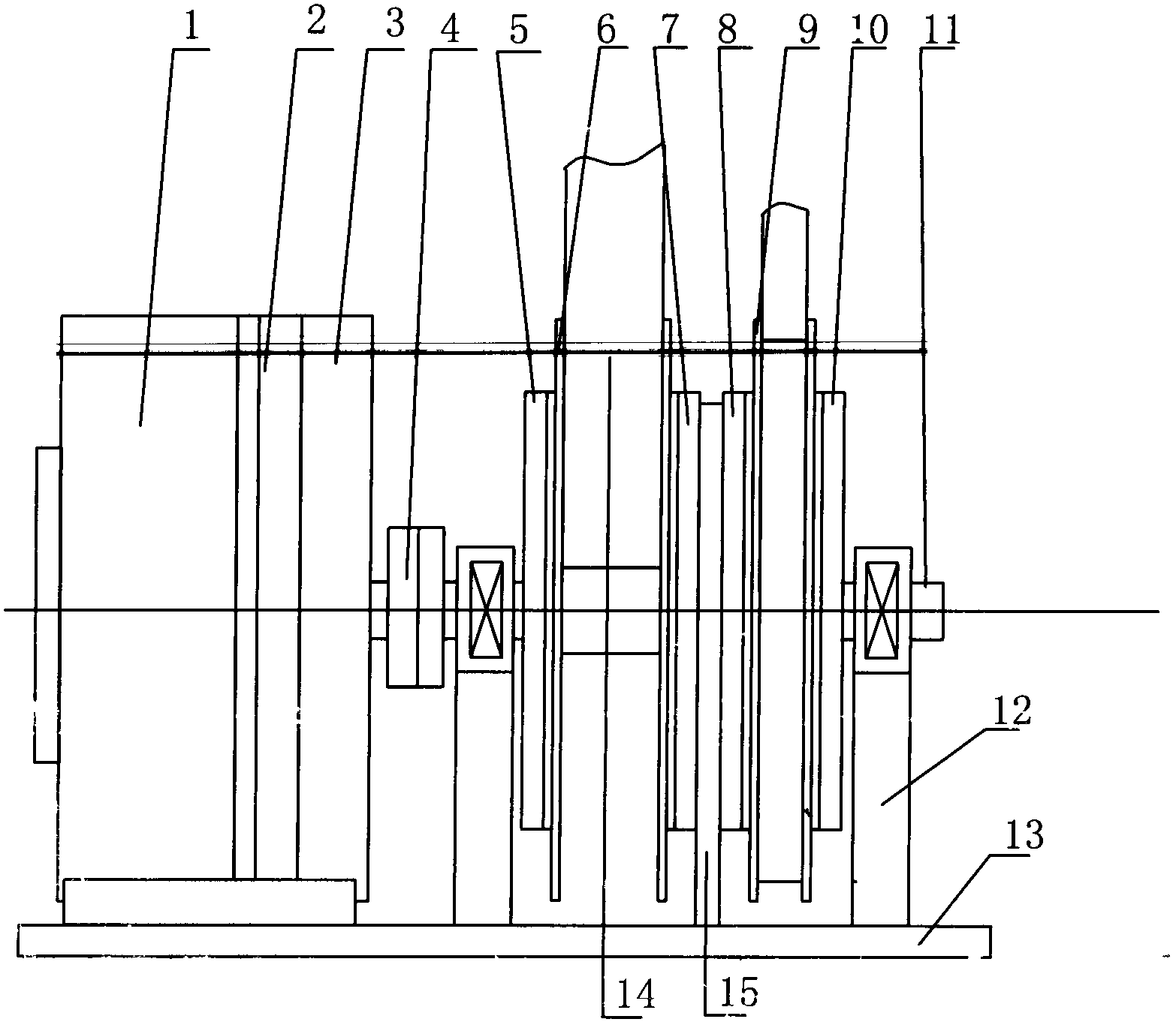
[0046] The design steps are as follows:

[0047] The carrier-based aircraft must obtain 30m / s on a 100-meter runway 2 Acceleration can take off, the aircraft takeoff speed and acceleration movement time calculation formula is as follows:

[0048] V=√(2aL)=√(200×30)≈77.46m / s (1)

[0049] t=√(2L / a)=√(200 / 30)≈2.58s (2)

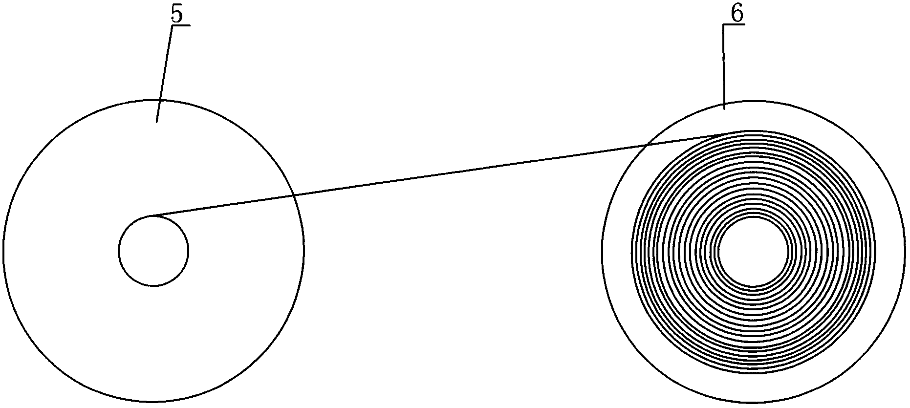
[0050] The length of the traction belt = the length of the runway, L = the sum of the lengths of the traction belts wound on the winch, the length of the traction belt

[0051] L = (L1 + L2 + ... LN) = 100 meters = the length of the ejection runway (3)

[0052] The formula for calculating the length of each layer of the traction belt of the winch: Li=3.14(D+2dn) (4)

[0053] D is the diameter of the winch shaft,

[0054] d = thickness of traction belt;

[0055] n = number of layers of traction belt

[0056] L=100=3.14[(D+2d1)+(D+2d2)+(D+2d3)+...(D+2dn)] (5)

[0057] The length of the known ejection track=the length of the traction belt=100 meters, ignore ...


PUM


Abstract

The invention provides a coaxial bidirectional winding accelerated shipboard aircraft catapult. A towing capstan and a returning capstan are coaxially arranged on a double-capstan winch of a catapult host; by an accelerated manner that the continuous winding diameter of a traction belt on the towing capstan is rapidly increased from small, a sliding shuttle on an ejection runway is dragged to implement the accelerated catapult-assisted take-off from a low speed to a high speed on a shipboard aircraft; the returning capstan drags the sliding shuttle on the ejection runway to rapidly and automatically return in the same accelerated manner that the continuous winding diameter is rapidly increased from small; instantaneous rotational kinetic energy of the towing capstan and the returning capstan are obtained from a spindle by electromagnetic clutches arranged at the lateral surfaces of the towing capstan and the returning capstan; and instantaneous braking energy of the towing capstan and the returning capstan is obtained by friction between the excircles of the towing capstan and the returning capstan and an electromagnetic brake arranged on a bed. The catapult has the advantages that the catapult is scientifically and reasonably designed, has a small volume, occupies a small space, has a simple structure and a large ejection power, is stable, safe and humanized to eject and not only can be used on various aircraft carriers, but also can be used as catapult-assisted take-off equipment for land-based airport short-distance runway airplanes or unmanned aerial vehicles.

Description

technical field [0001] The invention relates to the technical field of military equipment or carrier-based aircraft catapults, in particular to a coaxial bidirectional winding acceleration type carrier-based aircraft catapult. Background technique [0002] At present, there are three main ways for carrier-based aircraft to take off on an aircraft carrier: [0003] The first is the steam-type catapult used on the aircraft carrier of the U.S. military. The catapult uses steam as power to drive the towing hook to pull the aircraft to accelerate take-off through the piston in the open cylinder. The steam catapult equipment is bulky, takes up a lot of space, the manufacturing process is complicated, and consumes a lot of fresh water. Because the steam catapult in the United States uses a slotted cylinder, the steam leakage is large and the energy consumption is large. The cylinder seal uses The service life is short, and the maintenance cost is high. In severe cold regions or in...

Claims


Application Information

Patent Timeline
Patent Type & Authority Applications(China)
IPC IPC(8): B64F1/06
Inventor 姜明姜鹏李元贵
Owner 朱惠芬
Why Eureka
Try Eureka