Combined soot-blowing system

A soot blowing system and soot blower technology are applied in the treatment of combustion products, combustion methods, removal of solid residues, etc., which can solve hidden dangers affecting furnace efficiency, safe operation of heating furnaces, and can not well meet soot blowing requirements, etc. problem, to achieve the effect of improving furnace efficiency

Inactive Publication Date: 2013-02-06
SHAANXI QIYUAN TECH DEV
View PDF0 Cites 7 Cited by
  • Summary
  • Abstract
  • Description
  • Claims
  • Application Information

AI Technical Summary

Problems solved by technology

[0002] At present, the sootblowers used on direct tube heating furnaces are single-use, generally sonic sootblowers and pneumatic rotary sootblowers. The sootblowers of sonic sootblowers have a wide range of soot blowing, and there is no dead angle or dead zone. Smoke and dust will not form coking and scaling on the heating furnace, but the smoke and dust accumulate on the dense convection furnace tubes, which affects the furnace efficiency. The pneumatic rotary soot blower can blow the smoke and dust out of the furnace with the air flow, but the smoke and dust are easy to Coking and scaling on the furnace tube not only affects the furnace efficiency, but also poses hidden dangers to the safe operation of the heating furnace
Neither sonic sootblowers nor pneumatic rotary sootblowers are well suited for sootblowing requirements

Method used


Image

  • Combined soot-blowing system

Examples


Embodiment 1

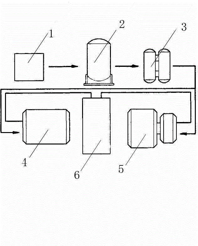
[0012] A combined soot blowing system according to the present invention includes an air compressor 1, an air storage tank 2, a dryer 3 and a heating furnace 6 connected in sequence, the heating furnace 6 is provided with a convection chamber, and the sonic soot blower 44 is arranged on The side of the convection chamber and the pneumatic rotary soot blower 5 are arranged on the front of the convection chamber. The combined soot blowing system also includes a control device, which is connected with the sonic soot blower 4 and the pneumatic rotary soot blower 5 respectively. connect.

[0013] When in use, first turn on the sonic soot blower 4 to crush the coke on the furnace tube for 30 minutes. During the period, the coke slag on the convection furnace tube is broken into powder, then turn off the sonic soot blower 4 and start the pneumatic rotation Type soot blower 5 makes the crushed powder out of the heating furnace 6 along with the furnace flue gas.


PUM


Abstract

The invention relates to a combined soot-blowing system and relates to a soot-blowing system applied to a heating furnace. The combined soot-blowing system comprises a sonic soot blower, a pneumatic rotary soot blower and a heating furnace. The heating furnace is provided with a convection chamber. The sonic soot blower is disposed on the side of the convection chamber, and the pneumatic rotary soot blower is disposed on the front side of the convection chamber. Coke on a furnace tube is crushed by the sonic soot blower, broken powder is discharged out of the heating furnace with hearth smoke by the pneumatic rotary soot blower, and the convection chamber furnace tube is cleaned well. Therefore, coke sag and soot are avoided, and furnace efficiency is improved.

Description

technical field [0001] The invention relates to a soot blowing system applied in a heating furnace. Background technique [0002] At present, the sootblowers used on direct tube heating furnaces are single-use, generally sonic sootblowers and pneumatic rotary sootblowers. The sootblowers have a wide range of soot blowing, and there is no dead angle or dead zone. Smoke and dust will not form coking and scaling on the heating furnace, but the smoke and dust accumulate on the dense convection furnace tubes, which affects the furnace efficiency. The pneumatic rotary soot blower can blow the smoke and dust out of the furnace with the air flow, but the smoke and dust are easy Coking and scaling on the furnace tube not only affects the furnace efficiency, but also poses hidden dangers to the safe operation of the heating furnace. Neither the sonic soot blower nor the pneumatic rotary soot blower can meet the soot blowing requirements very well. Contents of the invention [0003...

Claims


Application Information

Patent Timeline
IPC IPC(8): F23J3/02
Inventor 张淑芬
Owner SHAANXI QIYUAN TECH DEV
Why Eureka
Try Eureka