
Flow control method and apparatus for a continuous multiple zone mass transfer

A technology of mass transfer and equipment used in the preparation/purification of sulfur, separation methods, chemical instruments and methods, etc.

Active Publication Date: 2013-02-06
MERICHEM CO
View PDF5 Cites 0 Cited by
  • Summary
  • Abstract
  • Description
  • Claims
  • Application Information

AI Technical Summary

Problems solved by technology

The process gas preferably contains H 2 S and the second gas preferably contains oxygen

Method used


Image

  • Flow control method and apparatus for a continuous multiple zone mass transfer
  • Flow control method and apparatus for a continuous multiple zone mass transfer
  • Flow control method and apparatus for a continuous multiple zone mass transfer

Examples


Embodiment Construction

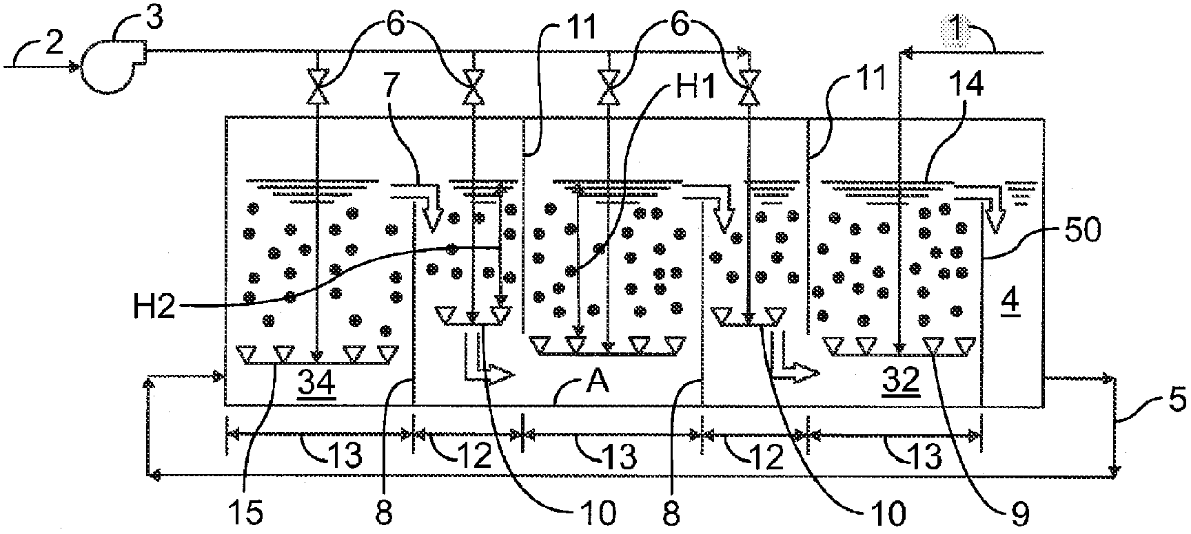
[0035] Now turn to the attached picture and first go to the figure 1 , illustrates an embodiment of the invention showing a gas distributor 10 inserted into one or more downcomers 12 connecting two mass transfer zones 13 . The distributor 10 is located above the bottom of the weir 11 . The gas is then injected into the sparger 10 . As the amount of injected gas increases, the gas-filled density of the liquid in the downcomer 12 will approach the gas-filled density of the liquid in the mass transfer zone 13 . The distributor 10 may be inserted into a downcomer 12 that separates two or more oxidation mass transfer zones and / or two or more process gas mass transfer zones. Below is an explanation of how the device controls the flow of the solution.

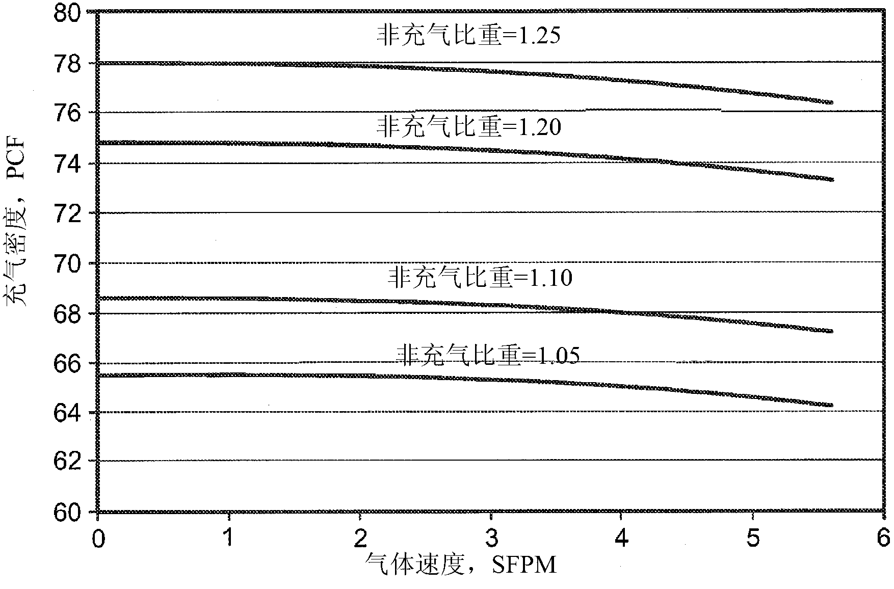
[0036] As mentioned above, the density of an aerated solution varies directly with the non-aerated density of the solution and inversely with the velocity of the gas passing through the solution. In other words, the higher the ga...


PUM


Abstract

The present invention relates to an apparatus and a method for contacting a liquid with different gases sequentially in separate mass transfer zones within a single vessel, the mass transfer zones operatively in fluid communication with each other, including intimately contacting the liquid with a process gas in co-current flow in a downstream mass transfer zone to effect mass transfer between the liquid and the process gas, and introducing the liquid into an upstream mass transfer zone with a second gas, different from the process gas, thereby effecting mass transfer between the liquid and the second gas. The rate of flow of the liquid from the upstream mass transfer zone to downstream mass transfer zone is controlled by the controlled addition of a third gas into one or more downcomers separating each mass transfer zone such that the specific density of the liquid in the downcomers provides a driving force that controls flow.

Description

[0001] Cross References to Related Applications [0002] This application claims the benefit of US Application Serial No. 12 / 794,875, filed June 7, 2010, which is hereby incorporated by reference in its entirety. technical field [0003] The present invention relates to a method and apparatus for contacting a liquid with a plurality of different gases sequentially in a gas-liquid contacting apparatus having a plurality of gas-liquid contacting zones, each gas-liquid contacting zone being in contact with at least one other gas-liquid in a single vessel The zones are in fluid communication for mass transfer between gas and liquid, in such a way that circulation of the solution occurs through the always existing density difference between the gas-liquid contact zone and the intermediate liquid-filled downcomer, without the use of a solution circulation pump. More particularly, the present invention relates to methods for the continuous removal of hydrogen sulfide gas (H 2 S) Me...

Claims


Application Information

Patent Timeline
Patent Type & Authority Applications(China)
IPC IPC(8): B01D53/52B01D53/75B01D53/79C01B17/05
CPCB01D2251/902B01D2255/20723B01D2251/102B01D2255/1021B01D53/79B01D2255/2047B01D53/75C01B17/05B01D2251/90B01D53/52B01D2255/20746B01D2255/20753B01D2251/904B01D2255/20776B01D2255/20738B01D2255/20761
Inventor 大卫·阿兰·霍布森
Owner MERICHEM CO
Learn More