
Wireless Power Transmission Device

A technology of wireless power transmission and electric power, applied in the direction of circuit devices, electrical components, etc., can solve problems such as difficulty in maintaining high-efficiency transmission characteristics

Active Publication Date: 2016-02-03
PANASONIC INTELLECTUAL PROPERTY MANAGEMENT CO LTD
View PDF5 Cites 0 Cited by
  • Summary
  • Abstract
  • Description
  • Claims
  • Application Information

AI Technical Summary

Problems solved by technology

[0009] In the wireless energy transmission circuit described in Patent Document 1, it is difficult to maintain high-efficiency transmission characteristics in the case of performing constant voltage operation from when a large power is transmitted to when a small power is transmitted

Method used


Image

  • Wireless Power Transmission Device
  • Wireless Power Transmission Device
  • Wireless Power Transmission Device

Examples


Embodiment 1

[0088] Hereinafter, Embodiment 1 of the present invention will be described.

[0089] The power transmitting antenna and the power receiving antenna are designed so that their resonance frequencies are both 0.55 MHz. The power transmission antenna was fabricated by connecting in series a first inductor having an inductance of 3.67 μH and a first capacitive element having a capacitance of 4100 pF. The power receiving antenna was fabricated by connecting in parallel a second inductor having an inductance of 3.67 μH and a second capacitive element having a capacitance of 4100 pF.

[0090] The first and second inductors are realized by twisted wires in which 120 copper wires each having a diameter of 75 μm are insulated and arranged in parallel. The shapes of the two inductors are circular with a diameter of 20cm, and the number of turns is set to 8. The unloaded Q value of the power transmission antenna (resonator) is 450. The power transmitting antenna and the power receiving...


PUM


Abstract

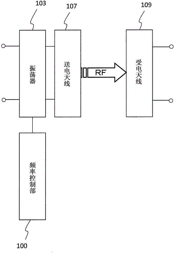
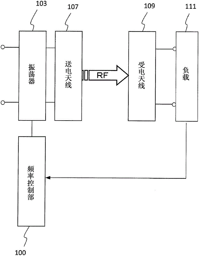
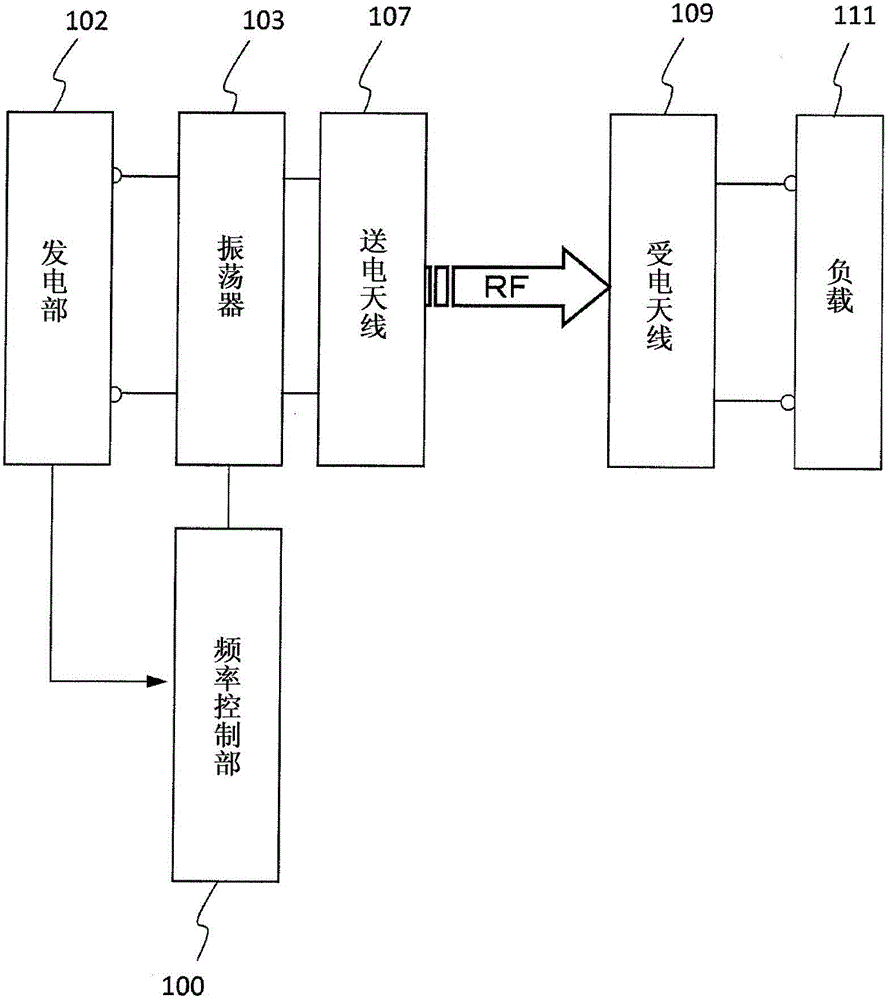
The wireless power transmission device of the present invention has a pair of antennas (107) and (109) and a control unit (100), and the pair of antennas (107) and (109) can transmit electric power in a non-contact manner through resonance magnetic field coupling of frequency f0 , one antenna is a series resonant circuit, the other antenna is a parallel resonant circuit, and the control unit (100) controls the transmission frequency according to the magnitude of power transmitted between the pair of antennas (107) and (109). When the electric power transmitted between the antennas is higher than the reference value P1, the control section (100) sets the transmission frequency to a value within the range of the first order of magnitude higher than the frequency f0; when the electric power is lower than the above-mentioned reference value P1, A control unit (100) sets the transmission frequency to a value within a second magnitude range lower than the first magnitude range.

Description

technical field [0001] The present invention relates to a resonant magnetic field coupling type non-contact power technology for wirelessly transmitting electric power using resonant magnetic field coupling. Background technique [0002] Patent Document 1 discloses a novel wireless energy transmission device that transmits energy via a space between two resonators. In this wireless energy transmission device, two resonators are coupled by the evanescent tail of vibration energy at a resonance frequency generated in the surrounding space of the resonators, whereby vibration energy is transmitted wirelessly (non-contact). [0003] In addition, electromagnetic induction technology has always existed. Among electronic devices using these power transmission technologies, many devices require that the voltage provided to the device be a constant voltage after receiving an input of constant voltage power and passing through some functional blocks such as power conversion or voltag...

Claims


Application Information

Patent Timeline
Patent Type & Authority Patents(China)
IPC IPC(8): H02J50/12H02J50/00
CPCH02J50/12H02J50/20H02J50/80
Inventor 菅野浩山本浩司
Owner PANASONIC INTELLECTUAL PROPERTY MANAGEMENT CO LTD
Learn More