Molding pipe split-flow mold

A technology for forming pipes and molds, which is applied to household appliances, tubular objects, and other household appliances, etc. It can solve the problems that the compression ratio cannot meet the comprehensive performance requirements of products, the density of plastic molding pipes is insufficient, and the molten material cannot form molecular structures, etc. , to achieve the effect of increasing density, increasing strength and hardness, and compact structure

Inactive Publication Date: 2013-02-13
SUZHOU JWELL MACHINERY
View PDF8 Cites 8 Cited by
  • Summary
  • Abstract
  • Description
  • Claims
  • Application Information

AI Technical Summary

Problems solved by technology

[0003] In order to improve production efficiency, a set of splitter molds is usually used in production to produce plastic molding pipes with different diameters and wall thicknesses, but the compression ratio of a set of splitter molds is limited. In actual production, it is often found that small and medium-sized plastic molding pipes can It meets the comprehensive performance requirements of the product, but when producing plastic molding pipes with special requirements such as large-diameter thick-walled or low-viscosity melts, the compression ratio can

Method used


Image

  • Molding pipe split-flow mold
  • Molding pipe split-flow mold

Examples


Embodiment Construction

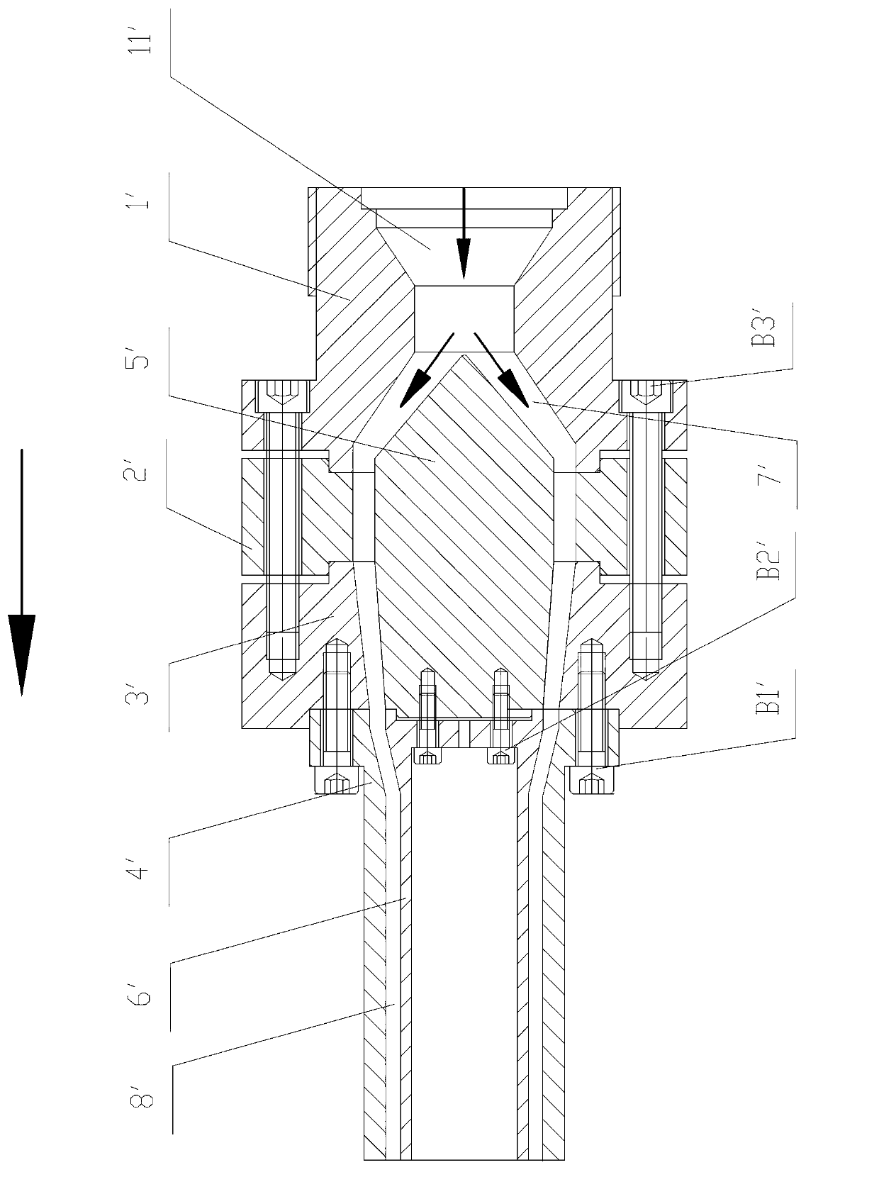
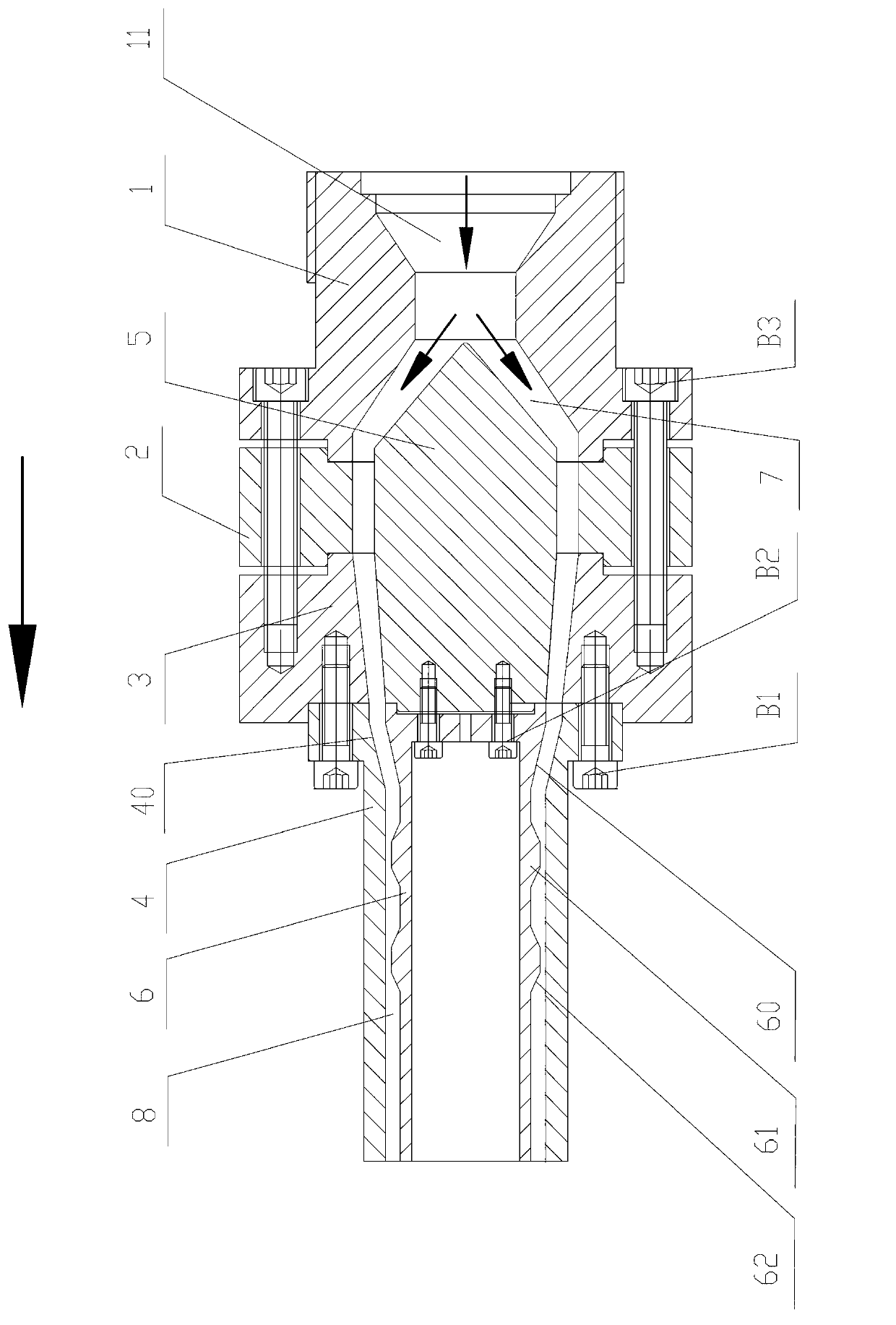
[0020] The present invention will be further described below in conjunction with the accompanying drawings and specific embodiments (the "front" described in this specification refers to the attached figure 1 The left side in the drawing is the direction indicated by the arrow on the attached drawing, and the "rear" refers to the right side in the attached drawing):

[0021] attached figure 2 It is the front view of the forming pipe splitter mold of the present invention, which includes a tail mold cover 1, a front mold cover 3, a transition bracket 2 fixedly connected between the tail mold cover 1 and the front mold cover 3, and the front end of the front mold cover 3 The mouth die 4 fixedly connected at the top, the shunt bracket 5 with a conical structure at the rear end and the mandrel 6 fixedly connected with the front end of the shunt bracket 5; 5 is accommodated in the inner cavity 7 of the tail die set 1, the transition bracket 2 and the front die set 3, the core die...


PUM


Abstract

The invention relates to a molding pipe split-flow mold which comprises a tail mold sleeve, a front mold sleeve, a transition support fixedly arranged between the tail mold sleeve and the front mold sleeve in a connecting mode, a mouth mold fixedly connected with a front end portion of the front mold sleeve, a split-flow support with a rear tail portion provided with a cone structure, and a core mold fixedly connected with a front end portion of the split-flow support. The split-flow support is contained in an inner cavity of the tail mold sleeve, an inner cavity of the transition support and an inner cavity of the front mold sleeve. The core mold is located in the mouth mold and coaxially arranged with the mouth mold. A flow pass used for passing of molten state materials is formed together between the outer wall face of the split-flow support and the inner wall face of the tail mold sleeve, the transition support and the front mold sleeve, and between the outer wall face of the core mold and the inner wall face of the mouth mold. At least one boss arching toward the flow pass is formed on the outer wall face of the core mold or the inner wall face of the mouth mold along the circumferential direction. The flow pass form a throat part with a decrescent cross section on the boss position. The molding pipe split-flow mold can improve density of molten materials in the flow pass, and enables intensity of molded plastic molding pipe products to be improved; and at the same time, utilization rate of a mold is also improved.

Description

technical field [0001] The invention relates to a diverting die used in the extrusion molding process of a forming pipe, in particular to a distributing die for molten material used before extrusion molding of a plastic forming pipe. Background technique [0002] attached figure 1 Described is the front view of the forming pipe splitter mold of the traditional technology, and the splitter mold includes the tail mold cover 1', the front mold cover 3', and the transition bracket 2 fixedly connected between the tail mold cover 1' and the front mold cover 3' ', a die 4' fixedly connected to the front end of the front die set 3', a shunt bracket 5' with a conical structure at the rear end, and a mandrel 6' fixedly connected to the front end of the shunt bracket 5'; the tail die The rear end of the sleeve 1' has a material feed port 11', the diverter bracket 5' is accommodated in the inner cavity 7' of the tail mold sleeve 1', the transition bracket 2' and the front mold sleeve 3...

Claims


Application Information

Patent Timeline
IPC IPC(8): B29C47/70B29C47/20B29L23/00B29C48/32
Inventor 何海潮王淳德
Owner SUZHOU JWELL MACHINERY
Why Eureka
Try Eureka