A Time Delay Compensation System

A technology of delay compensation and delay circuit, which is applied in baseband system components, electromagnetic transceivers, optical fiber transmission, etc., can solve the problems of heavy weight, poor anti-interference performance, and large volume, and achieve light weight, high precision, and small size effect

Active Publication Date: 2015-12-16
深圳市虹远通信有限责任公司
View PDF4 Cites 0 Cited by
  • Summary
  • Abstract
  • Description
  • Claims
  • Application Information

AI Technical Summary

Problems solved by technology

[0003] In order to solve the technical problems of poor anti-interference performance, large volume and heavy weight in the existing time delay compensation system, the present invention provides a time delay compensation system

Method used


Image

  • A Time Delay Compensation System
  • A Time Delay Compensation System

Examples


Embodiment Construction

[0018] The present invention will be further described below in conjunction with the accompanying drawings and specific embodiments.

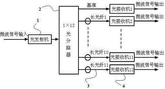
[0019] Such as figure 1 As shown, the delay compensation system of the embodiment of the present invention includes an optical transmitter 1, an optical splitter 2 connected to the optical transmitter 1, several optical fiber lines 3 and several optical receivers 4, and several optical fiber lines 3 One end of each is respectively connected to each output of the optical splitter 2 , and the other end is respectively connected to an input end of a corresponding optical receiver 4 .

[0020] The time delay compensation system of the present invention includes at least two optical fiber lines 3, one of which is a reference time delay line, and the other optical fiber lines 3 are long optical fibers, and the lengths of all the long optical fibers are different. In this example, if figure 1 As shown, the optical splitter uses a 1-to-12 optical spl...


PUM


Abstract

The invention provides a time delay compensation system which comprises an optical transmitter, an optical branching device connected with the optical transmitter, a plurality of optical fiber cables, and a plurality of photo receivers. One end of each optical fiber cable is connected with one output end of the optical branching device, and the other end of each optical fiber cable is connected with an input end of one photo receiver. Due to the fact that electrical signals are converted to optical signals to be transmitted, the time delay compensation system is strong in ability to resist electromagnetic interference and high in transmission stability. Moreover, the time delay compensation system is small in size and light in weight.

Description

technical field [0001] The invention relates to a time delay compensation system used in communication, radar, instrumentation and the like. Background technique [0002] In the existing time delay compensation system, one is to use cables to compensate the time delay, and the other is to use a time delay filter to compensate the time delay. The delay compensation system using cables has the disadvantages of huge size, heavy weight, large difference between low-frequency and high-frequency transmission signals, troublesome adjustment of delay, insufficient delay accuracy, and poor anti-interference performance; Although the compensation system is small in size and light in weight, its spectral response is not enough, the range of delay adjustment is small and cumbersome, the delay accuracy can only be controlled at the nanosecond level, and its anti-interference performance is poor. Contents of the invention [0003] In order to solve the technical problems of poor anti-i...

Claims


Application Information

Patent Timeline
Patent Type & Authority Patents(China)
IPC IPC(8): H04B10/25H04B10/40H04L25/02
Inventor 林凯
Owner 深圳市虹远通信有限责任公司
Why Eureka
Try Eureka