

Measuring system of three-dimensional shape of strong reflecting surface based on high dynamic strip projector
A measurement system and three-dimensional topography technology, applied in measurement devices, instruments, optical devices, etc., can solve the problem of inability to effectively measure measurement accuracy, and achieve high measurement accuracy and adaptability to overcome the influence of background light on measurement. Effect
- Summary
- Abstract
- Description
- Claims
- Application Information
AI Technical Summary
Problems solved by technology
Method used
Image

Examples
Embodiment Construction
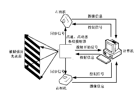
[0015] See figure 1 , The present invention is a three-dimensional topography measurement system for strongly reflective surfaces based on a high dynamic stripe projector, including a computer, a high dynamic stripe projector and an image acquisition unit. The system sends projection control information to the high dynamic stripe projector through the computer to control it to project stripe images with different brightness and different gray scales. At the same time, the computer sends control information to the image acquisition unit to control the image acquisition unit to shoot at different exposure times. Among them, the high dynamic stripe projector and the image acquisition unit are connected through a synchronous trigger signal to ensure real-time synchronization of the projected image and the captured image; after the shooting is completed, the image acquisition unit transmits the collected image information to the computer, and the computer processes the image. The t...
PUM
 Abstract
Description
Claims
Application Information