Ultrasound probe head comprising an imaging transducer with a shielding element

A technology for imaging transducers and ultrasonic probes, which can be used in shielding, ultrasonic therapy, and parts of instruments to solve problems such as damage to imaging transducers

Active Publication Date: 2013-02-20
THERACLION
View PDF9 Cites 5 Cited by
  • Summary
  • Abstract
  • Description
  • Claims
  • Application Information

AI Technical Summary

Problems solved by technology

[0007] One problem with known probes is that reflected ultrasound waves from the therapy transducer can damage the imaging transducer

Method used


Image

  • Ultrasound probe head comprising an imaging transducer with a shielding element
  • Ultrasound probe head comprising an imaging transducer with a shielding element
  • Ultrasound probe head comprising an imaging transducer with a shielding element

Examples


Embodiment Construction

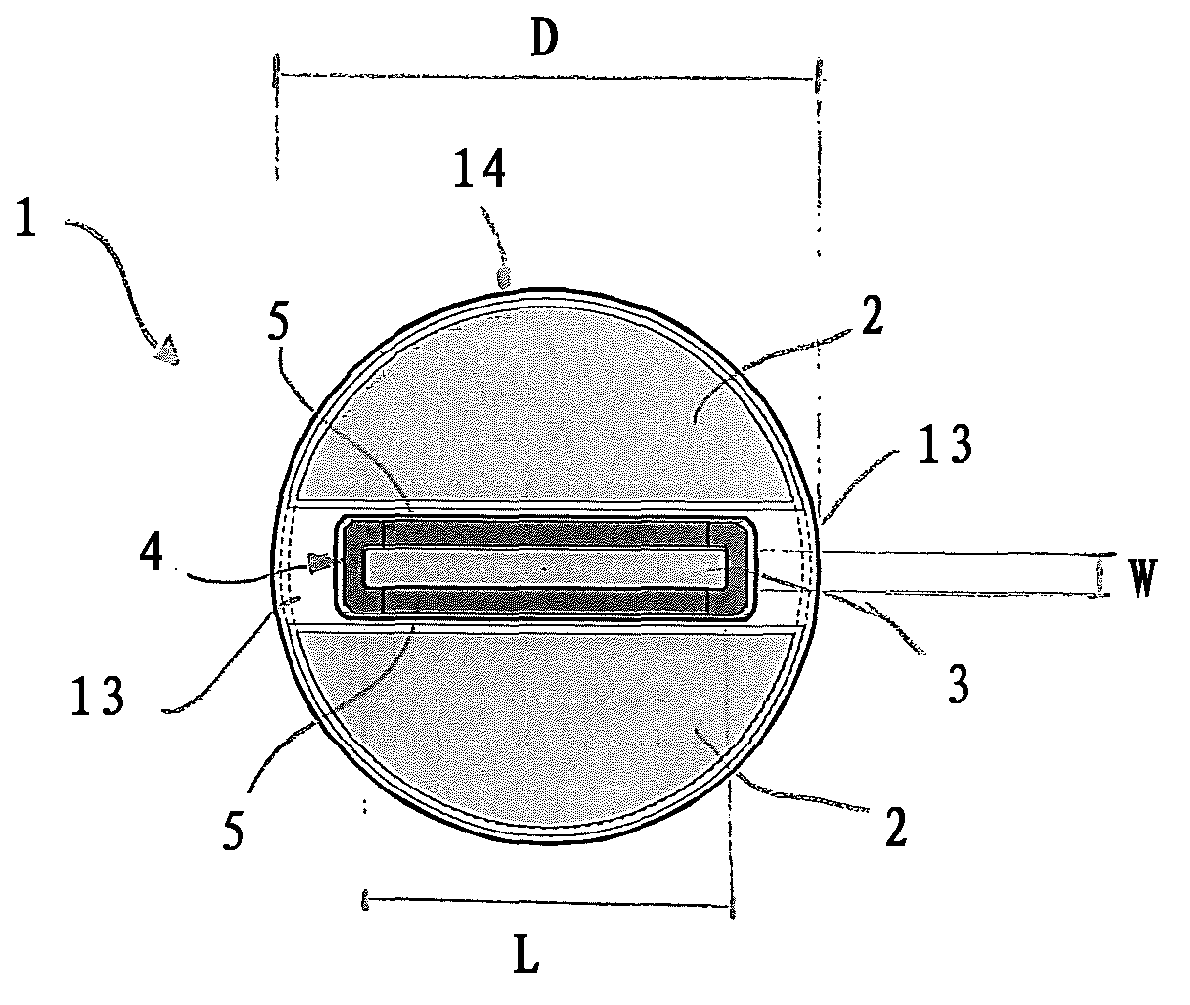
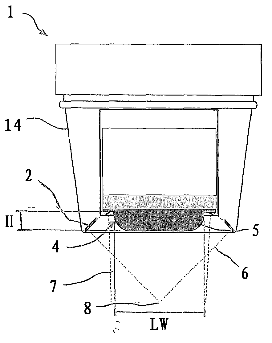
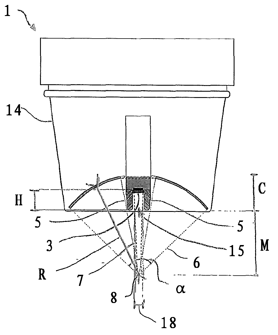
[0052] figure 1 An embodiment of the probe 1 according to the invention is shown from the side facing the patient's skin during treatment. The probe 1 has a circular cross-section with a diameter D and comprises a therapy transducer 2 and an imaging transducer 3 . The therapy transducer 2 is preferably a HIFU transducer shaped as a spherical cap (see also Figure 2b ). When placed on the patient's skin, the therapeutic transducer 2 has a concave curvature, ie the transducer bends away from figure 1 The observer direction in . The radius of curvature R of the therapeutic transducer 2 , its aperture angle a and its diameter D are chosen to enable focusing of ultrasound waves at a focal point at a specific distance relative to the transducer in a manner known to those skilled in the art. The imaging transducer 3 is positioned symmetrically on the therapy transducer 2 and has a rectangular shape. In this embodiment, the imaging transducer 3 does not span the entire diameter D...


PUM


Abstract

The present invention relates to an ultrasound probe head (1), especially for HIFU treatment, comprising a treatment ultrasound transducer (2) and an imaging ultrasound transducer (3). The imaging transducer (3) comprises a shield element (4) configured such that most of the energy of ultrasound waves (10) reflected in the direction of the imaging transducer (3) are held back by said shield element (4). The shield element (4) is configured in such a way as not to interfere with the emission of the imaging ultrasound waves (7).

Description

technical field [0001] The present invention relates to an ultrasound probe for treating an organ or tissue according to claim 1 , an ultrasound device according to claim 10 and a method of reducing damage to an imaging transducer according to claim 14 . Background technique [0002] High-intensity focused ultrasound (HIFU) therapy can be used to destroy target tissue or tumors. By applying very high intensity ultrasound waves to the targeted area, the cells are severely damaged or destroyed. This is mainly caused by the heat generated in the target area by ultrasound. Cavitation effects and mechanical vibrations caused by ultrasound can further cause additional damage to cells. [0003] Typically, HIFU is capable of 500W / cm at the focal point 2 up to 50kW / cm 2 Ultrasound with an intensity in the range of approximately 0.2 MHz to 3.5 MHz. [0004] HIFU therapy is usually achieved by a therapy transducer that has lenses or is shaped itself to focus the therapy ultrasound...

Claims


Application Information

Patent Timeline
Patent Type & Authority Applications(China)
IPC IPC(8): A61N7/02
CPCA61N7/02A61B8/13A61B2019/5276A61B8/4494A61B8/4444A61B8/4483A61B2090/378B33Y70/00B33Y80/00A61B8/00G12B17/02
Inventor F·拉考斯特
Owner THERACLION
Why Eureka
Try Eureka