Application of raney nickel as slurry reactor to synthesize methane catalyst

A technology for synthesizing methane and a catalyst is applied in the application field of Raney nickel as a slurry bed methanation catalyst, which can solve problems such as increased catalyst wear, high reaction temperature, and catalyst pore structure damage, and achieves the effect of avoiding energy consumption

Inactive Publication Date: 2013-02-27
TAIYUAN UNIV OF TECH +1
View PDF5 Cites 19 Cited by
  • Summary
  • Abstract
  • Description
  • Claims
  • Application Information

AI Technical Summary

Problems solved by technology

However, the slurry bed methanation process and the fixed bed process have different requirements on the catalyst, so the use of industrial fixed bed catalysts in the slurry bed methanation reaction has many disadvantages, which are specifically reflected in: (1) the particle size of the catalyst required by the slurry bed Smaller and more uniform, but the fixed bed methanation catalyst has a large particle size, so the industrial catalyst needs to be broken, which will lead to the destruction of the pore structure of the catalyst; (2) the industrial fixed bed methanation catalysts are all supported nickel-based catalysts, Must pass H before reacting 2 For

Method used


Image

  • Application of raney nickel as slurry reactor to synthesize methane catalyst
  • Application of raney nickel as slurry reactor to synthesize methane catalyst
  • Application of raney nickel as slurry reactor to synthesize methane catalyst

Examples


Embodiment 1

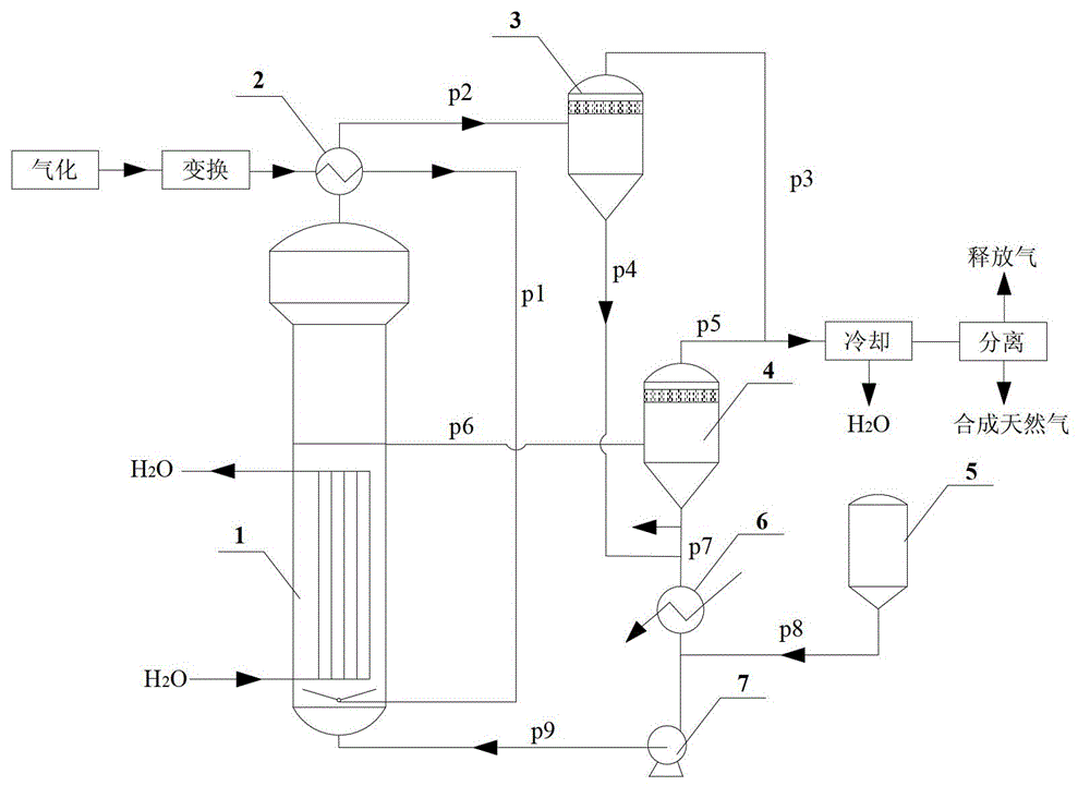
[0031] Ni 93 al 5 Mo 2 Raney nickel catalyst is mixed with paraffin in the catalyst storage tank, and the control Raney nickel concentration is 2wt%, and is pressed in the slurry state bed methanation reactor by circulation pump 7 from the bottom through pipeline p1, then passes into (V% ): H 2 66.53%, CH 4 12%, N 2 1%, CO 19.47%, CO 2 1% synthesis gas, the pressure is raised to 1Mpa, and the temperature is raised to 250°C to start the reaction. The air velocity of the feed gas is 1000L / (h kg), and the tail gas enters the gas-liquid separator I from the top of the reactor through the pipeline p3. The liquid components and catalysts entrained in the tail gas are discharged from the bottom of the separator I, and merged with the pipe p8 through the pipeline p5, and the tail gas is discharged from the top of the gas-liquid separator I to obtain synthetic natural gas after cooling and purification. During the methanation reaction, the inert liquid phase medium containing...

Embodiment 2~11

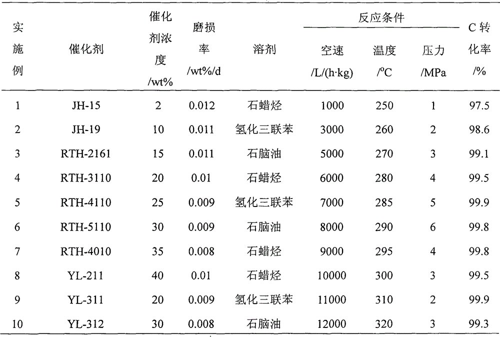
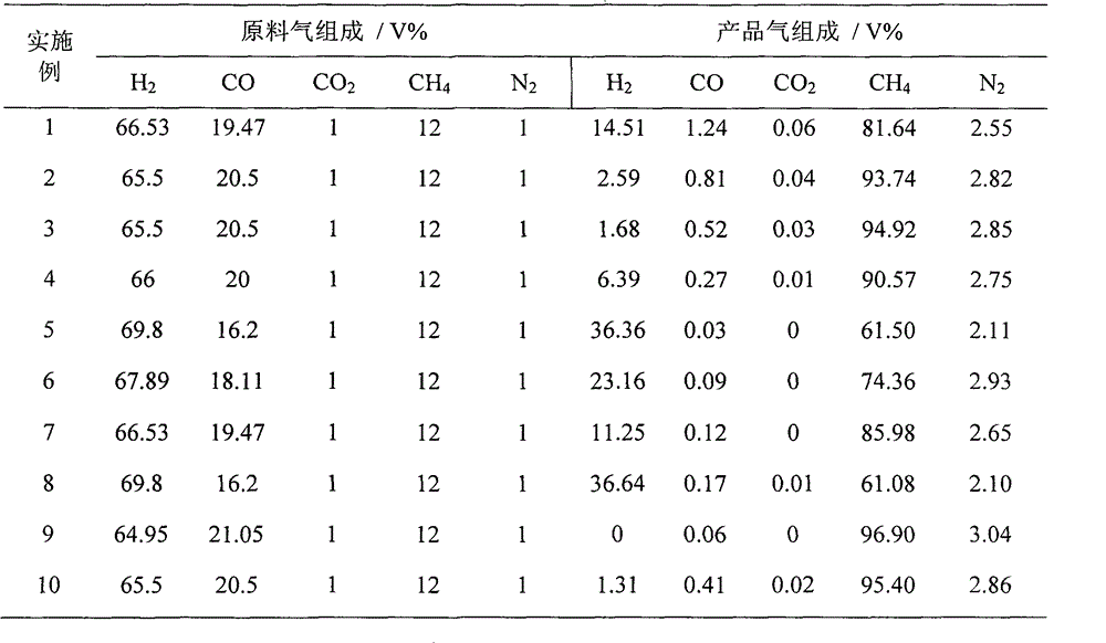
[0033] On the basis of Example 1, Examples 2-11 adjusted the catalyst type, the concentration of the catalyst in the slurry bed methanation reactor, the type of inert liquid medium, the reaction gas space velocity, the reaction temperature, and the reaction pressure factors. , see attached table 1 for specific data and results, and attached table 2 for composition of feed gas and product gas.


PUM


Abstract

The invention provides the application of raney nickel as a slurry reactor to synthesize a methane catalyst, including: adding a raney nickel catalyst dispersed in an inert liquid medium to a reactor for a methanation reaction, feeding product gas and raw material gas to a separator, discharging a liquid phase component I composed of the liquid phase component and the catalyst component in the product gas from the bottom of the separator I, discharging gas phase I from the top of the separator, discharging a part of the inert liquid medium containing the catalyst from the middle of the reactor into a separator II, discharging gas phase II from the top of the separator II, mixing the gas phase II with the gas phase I to get a natural gas product, discharging the inert liquid medium of the catalyst from the bottom of the separator II to mix with the liquid phase component I to get a mixture, and feeding the mixture and the fresh methanation catalyst dispersed in the inert liquid medium together into the reactor for the methanation reaction. The application has the advantages that the raney nickel catalyst does not need reduction, has high mechanical strength and good wear resistance, and can satisfy the requirement of slurry reactor methanation process for low temperature activity.

Description

technical field [0001] The invention belongs to the use of Raney nickel (Raney-Ni), in particular to the application of Raney nickel as a slurry bed methanation catalyst. Background technique [0002] my country is rich in coal, poor in oil, and low in gas energy, so the comprehensive optimization and utilization of coal resources is imminent. Coal-to-synthetic natural gas can not only meet the current growing demand for clean energy, but also play an irreplaceable role in the rational utilization and optimal allocation of domestic coal resources. Methanation is the core technology of coal-to-natural gas, the reaction refers to CO or CO 2 Synthesis of CH by hydrogenation under the action of catalyst 4 and H 2 O, the reaction formula is as follows: [0003] CO+3H 2 =CH 4 +H 2 O+206KJ / mol (1) [0004] CO 2 +4H 2 =CH 4 +2H 2 O+165KJ / mol (2) [0005] At present, the coal-to-natural gas technologies in the world mainly include LURGI in Germany, DAVY in the UK and Top...

Claims


Application Information

Patent Timeline
IPC IPC(8): C10L3/08
Inventor 李忠范辉张庆庚闫少伟崔晓曦
Owner TAIYUAN UNIV OF TECH
Why Eureka
Try Eureka