
Novel air-cooled condenser for brewing wine

An air-cooled condenser, a new technology, applied in the preparation of alcoholic beverages, etc., can solve the problems of poor cooling effect, complicated structure of water-cooled equipment, and inability to produce high-temperature wine, etc., to maintain traditional flavor and simple structure , clear effect

Active Publication Date: 2014-04-16
SHAOXING CHITULONG MASCH TECH CO LTD
View PDF5 Cites 1 Cited by
  • Summary
  • Abstract
  • Description
  • Claims
  • Application Information

AI Technical Summary

Problems solved by technology

However, the water-cooling method has the following defects: first, the cooling effect is not ideal; second, the water consumption is huge, especially the water after cooling is directly discharged, resulting in waste of water resources and high cost; third, the structure of the water-cooling equipment is complex, Difficult to operate and low production capacity; Fourth, the temperature of the wine in the brewing industry is extremely important, it must be controlled and kept constant, otherwise the quality of the wine obtained will be greatly reduced, and the water cooling method cannot well meet the above needs
Someone later developed an air-cooled cooling method, but the cooling effect is not a good choice. According to the process requirements, it is a supercooled type, which cannot produce high-temperature wine, but can only produce low-temperature wine, and the adaptability is not strong; and the above-mentioned water-cooled method The fourth shortcoming has not been well overcome

Method used


Image

  • Novel air-cooled condenser for brewing wine
  • Novel air-cooled condenser for brewing wine
  • Novel air-cooled condenser for brewing wine

Examples


Embodiment Construction

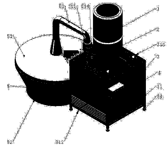
[0028] Such as Figure 1 to Figure 3 Shown is a preferred embodiment of the present invention.

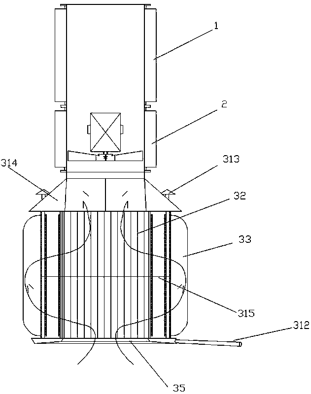
[0029] Such as figure 1 As shown, a new type of air-cooled condenser for brewing, including a muffler 1, a fan 2 and a cooling chamber 3, which are connected in sequence from top to bottom. There is a distiller's grain vapor inlet 311 above the cooling chamber, and an air inlet below the cooling chamber. The above-mentioned structure is the prior art in this field, and will not be described in detail this time. The noise of the fan is the noise source of the equipment. In order to reduce the environmental pollution of the workshop, a muffler is installed at the air outlet to control the noise of the fan at about 60dB (A). In the embodiment, a fan with multiple blades and low noise is selected to reduce the noise of the fan to 60 dB(A).

[0030] Such as figure 2 , image 3 As shown, the cooling chamber includes an outer frame 31 and a plurality of rows of heat exchange tubes 3...


PUM


Abstract

The invention discloses a novel air-cooled condenser for brewing wine. The air-cooled condenser comprises a silencer, a draught fan and a cooling chamber which are connected from the top down. A vinasse steam inlet is disposed above the cooling chamber; and an air inlet is disposed below the cooling chamber. The cooling chamber comprises an outer framework and a plurality of rows of heat exchange tubes vertically arranged in the outer framework; an air inlet chamber communicated with the upper opening of each heat exchange tube is arranged at upper portion close to the side of the out framework; the air inlet chamber is communicated with vinasse steam inlet; an airflow change direction baffle is disposed at the middle position of the heat exchange tubes in the outer framework; the lower opening of each heat exchange tube is communicated with a lower wine-collecting tank capable of collecting wine liquid; a wine outlet communicated with the lower wine-collecting tank is disposed at the side wall close to the bottom of the outer framework; and the bottom of the lower wine-collecting tank is low close to the wine inlet and high far away from the wine outlet. The technical solution is unique and simple in structure and convenient for operation, and has relatively good cooling effect, large cooling amount and high work efficiency.

Description

technical field [0001] The invention relates to the field of brewing equipment, in particular to a novel air-cooled condenser for brewing. Background technique [0002] The traditional liquor-making process is as follows: raw materials—soaking—first steaming—braised grains—re-steaming—out of the retort and spread out to cool—adding koji—packing and cultivating bacteria—with leesbarrel fermentationdistillation (cooling)—finished wine. Among them, the distillation step plays the role of separation and concentration, sterilization and disinfection in the brewing process, and keeps the mellow fragrance lingering through the heating reaction to maintain the characteristics of liquor; while the cooling step is to convert the gas into liquid (turn the distilled distiller's grain gas into into liquor). Whether the cooling effect is good or not is related to the quantity of wine produced, production efficiency, the output value of the enterprise, and so on. [0003] The tradition...

Claims


Application Information

Patent Timeline
Patent Type & Authority Patents(China)
IPC IPC(8): C12G3/12C12H6/02
Inventor 朱忠林
Owner SHAOXING CHITULONG MASCH TECH CO LTD
Learn More