Steel-ultra-high performance concrete combined bridge deck structure with shearing resisting structure and construction method thereof

A technology of ultra-high performance and combined bridge deck, which is applied in the direction of bridges, bridge parts, bridge materials, etc., can solve the problem that it is difficult to meet the application requirements of thin ultra-high performance concrete layers, difficult to realize thin ultra-high performance concrete layers, and shear key structures Large size and other issues, to achieve the effect of good operability and economy, strong flexibility and adaptability, and high shear strength

Active Publication Date: 2015-04-01
HUNAN UNIV
View PDF7 Cites 2 Cited by
  • Summary
  • Abstract
  • Description
  • Claims
  • Application Information

AI Technical Summary

Problems solved by technology

However, it is difficult to achieve a thin ultra-high performance concrete layer on the steel bridge deck if the traditional shear structure is adopted, mainly because of the high height of the traditional shear key
Therefore, for the application of ultra-high performance concrete to the steel bridge deck, the shear structure used in the traditional steel-concrete composite structure has the disadvantages of large shear key structure size and cumbersome construction technology, which is difficult to meet the requirements of the thin ultra-high performance concrete layer. Application requirements in steel bridge decks

Method used


Image

  • Steel-ultra-high performance concrete combined bridge deck structure with shearing resisting structure and construction method thereof
  • Steel-ultra-high performance concrete combined bridge deck structure with shearing resisting structure and construction method thereof
  • Steel-ultra-high performance concrete combined bridge deck structure with shearing resisting structure and construction method thereof

Examples


Embodiment 1

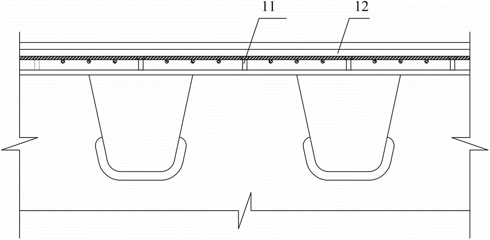
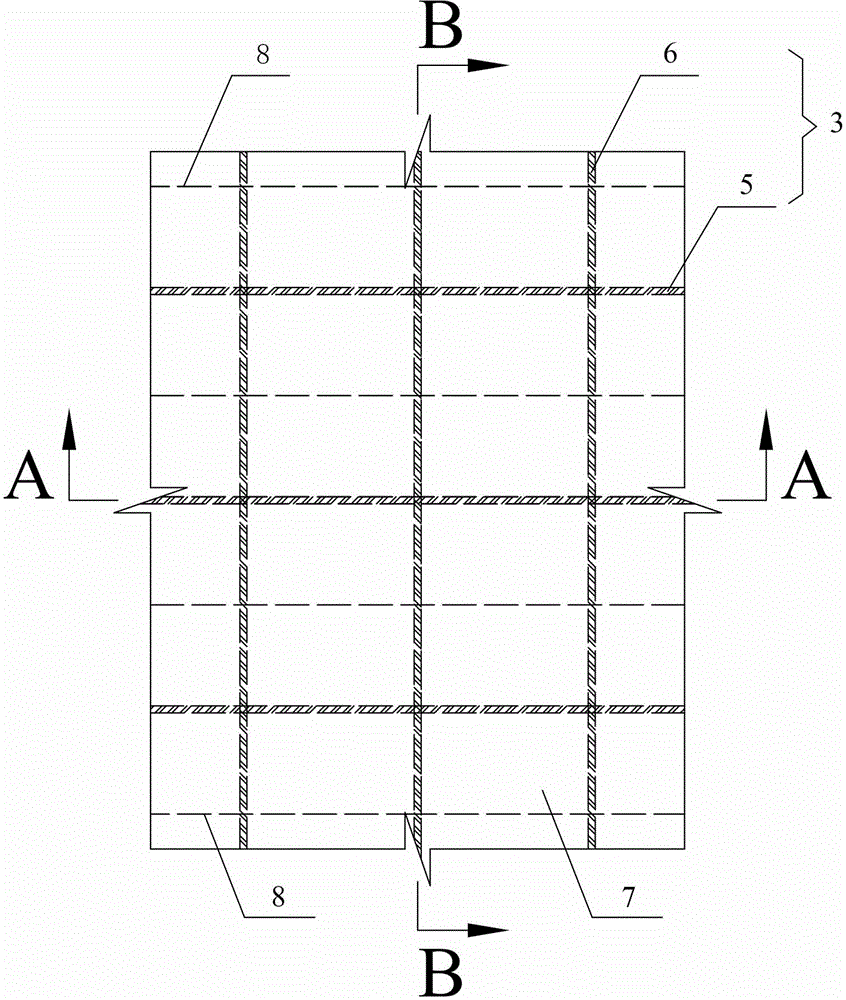
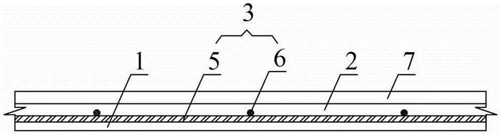
[0044] A sort of Figure 2 ~ Figure 4 The steel-ultra-high-performance concrete composite deck structure containing the shear structure of the present invention is shown, and the composite deck structure includes the steel bridge deck layer 1 below and the ultra-high-performance concrete layer poured on the steel bridge deck layer 1 2. The lower part of the steel bridge deck layer 1 is provided with longitudinal rib webs 8 , and the steel mesh shear structure 3 is welded above the steel bridge deck layer 1 , and the steel mesh shear structure 3 is embedded in the ultra-high performance concrete layer 2 . The steel mesh shear structure 3 is a double-layer superimposed steel bar composite structure. The double-layer superimposed steel bar composite structure includes a longitudinal bar distribution layer welded on the top surface of the steel bridge deck layer 1 and a transverse bar distribution layer welded above the longitudinal bar distribution layer. The longitudinal bar dis...

Embodiment 2

[0051] A sort of Figure 5 ~ Figure 7 The steel-ultra-high-performance concrete composite deck structure containing the shear structure of the present invention is shown, and the composite deck structure includes the steel bridge deck layer 1 below and the ultra-high-performance concrete layer poured on the steel bridge deck layer 1 2. The lower part of the steel bridge deck layer 1 is provided with longitudinal rib webs 8 , and the steel mesh shear structure 3 is welded above the steel bridge deck layer 1 , and the steel mesh shear structure 3 is embedded in the ultra-high performance concrete layer 2 . The steel mesh shear structure 3 is a double-layer superimposed steel bar composite structure. The double-layer superimposed steel bar composite structure includes a longitudinal bar distribution layer welded on the top surface of the steel bridge deck layer 1 and a transverse bar distribution layer welded above the longitudinal bar distribution layer. The longitudinal bar dis...

Embodiment 3

[0058] A sort of Figure 8 ~ Figure 10 The steel-ultra-high-performance concrete composite deck structure containing the shear structure of the present invention is shown, and the composite deck structure includes the steel bridge deck layer 1 below and the ultra-high-performance concrete layer poured on the steel bridge deck layer 1 2. The lower part of the steel bridge deck layer 1 is provided with longitudinal rib webs 8 , and the steel mesh shear structure 3 is welded above the steel bridge deck layer 1 , and the steel mesh shear structure 3 is embedded in the ultra-high performance concrete layer 2 . The steel mesh shear structure 3 is a three-layer superimposed steel bar composite structure. The three-layer superimposed steel bar composite structure includes a transverse reinforcement distribution layer welded on the top surface of the steel bridge deck layer 1, a longitudinal reinforcement distribution layer welded above the transverse reinforcement distribution layer, ...


PUM


Abstract

The invention discloses a steel-ultra-high performance concrete combined bridge deck structure with a shearing resisting structure and a construction method thereof. The structure comprises a steel bridge deck layer and an ultra-high performance concrete layer, wherein a shearing-resisting reinforcing mesh structure is fixedly connected with the steel bridge deck layer; and the shearing-resisting reinforcing mesh structure is embedded in the ultra-high performance concrete layer. The construction method comprises the following steps of: firstly, erecting a steel beam so as to obtain the steel bridge deck layer; secondly, constructing and welding a reinforcing mesh, wherein the reinforcing mesh can adopt the mode that a lower longitudinal rib distributed layer is combined with an upper transverse rib distributed layer, or a mode that a lower transverse spacing rib distributed layer, a longitudinal rib distributed layer and the upper transverse rib distributed layer are combined, and longitudinal reinforcing ribs and transverse reinforcing ribs can be arranged among shearing-resisting longitudinal ribs and shearing-resisting transverse ribs; subsequently casting the ultra-high performance concrete layer so as to embed the shearing-resisting reinforcing mesh structure into the ultra-high performance concrete layer; and finally paving a wearing layer so as to accomplish the construction. The steel-ultra-high performance concrete combined bridge deck structure has the advantages of being small in building height, large in partial rigid, reliable in shearing-resisting connection between combined layers, good in fatigue resistance, convenient to construct and the like.

Description

technical field [0001] The invention relates to a building detail of a bridge structure and its construction, in particular to a combined bridge deck structure and its construction method. Background technique [0002] Compared with steel bridge asphalt concrete pavement, steel bridge cement concrete pavement has the advantages of high local stiffness of the bridge deck and high fatigue life, so it is gradually adopted. In the existing steel bridge cement concrete bridge deck pavement, the shear structure adopts shear key methods such as studs, steel connectors, and PBL connectors, such as figure 1 Shown (taking the peg as an example of a conventional shear key 11). The height of the conventional shear key 11 in the conventional shear-resistant structure is large, which leads to an increase in the thickness of the cement concrete pavement layer 12 of the steel bridge, which causes an increase in the dead load of the bridge deck and reduces the economy. At the same time, th...

Claims


Application Information

Patent Timeline
Patent Type & Authority Patents(China)
IPC IPC(8): E01D19/12E01D21/00E01D101/26E01D101/30
Inventor 邵旭东曹君辉李嘉周环宇张哲黄政宇
Owner HUNAN UNIV
Why Eureka
Try Eureka