Torque motor torque fluctuation coefficient detector and detecting method

A technology of torque fluctuation and torque motor, applied in the direction of torque measurement, instruments, measuring devices, etc., can solve the problem of unreliable test results, and achieve the effect of good man-machine interface, simple and convenient operation, scientific and reasonable structure

Inactive Publication Date: 2013-02-27
HARBIN INST OF TECH
View PDF6 Cites 17 Cited by
  • Summary
  • Abstract
  • Description
  • Claims
  • Application Information

AI Technical Summary

Problems solved by technology

[0006] The invention aims to solve the problem that the detection result is unreliable due to the gravitational interference of the stator itself in the process of measuring the force of the stator to the sensor by the existing torque motor torque fluctuation coefficient detector, and provides a torque motor torque fluctuation coefficient Detector and detection method

Method used


Image

  • Torque motor torque fluctuation coefficient detector and detecting method
  • Torque motor torque fluctuation coefficient detector and detecting method
  • Torque motor torque fluctuation coefficient detector and detecting method

Examples


specific Embodiment approach 1

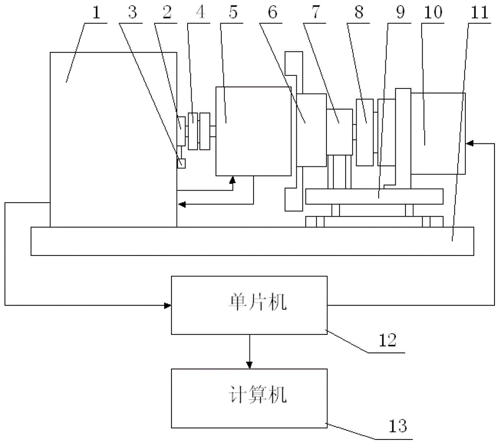
[0029] Specific implementation mode one: the following combination Figure 1 to Figure 3 Describe this embodiment, the torque motor torque fluctuation coefficient detector described in this embodiment includes a dynamometer 1, and is characterized in that: it also includes a calibration assembly, a first shaft coupling 4, a measured torque motor 5, a card Disk manipulator 6, bearing bearing 7, second shaft coupling 8, position adjustment base 9, stepper motor 10, stable base 11, single-chip microcomputer 12 and computer 13,

[0030] The dynamometer 1 is fixed on the stable base 11, the output shaft of the dynamometer 1 passes through the calibration assembly and is connected with the rotating shaft of the rotor of the torque motor 5 under test through the first coupling 4,

[0031] The power output shaft of the stepper motor 10 is connected to the central axis of the chuck manipulator 6 through the second shaft coupling 8, and the chuck manipulator 6 is used to firmly clamp th...

specific Embodiment approach 2

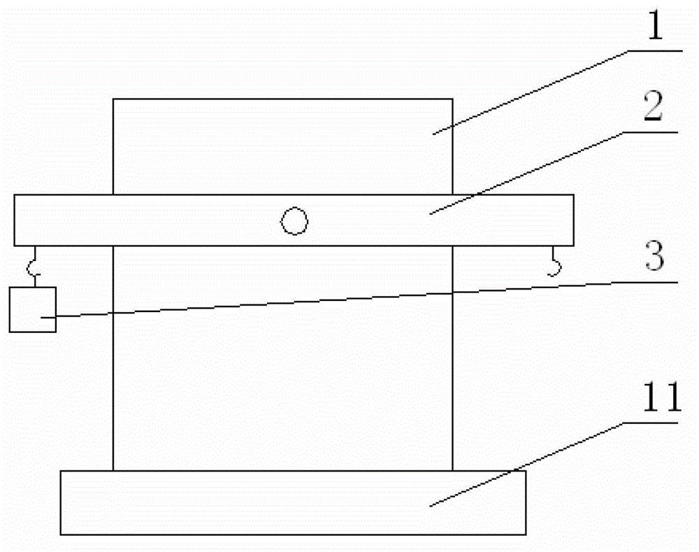
[0039] Specific implementation mode two: the following combination figure 1 and figure 2 Describe this embodiment. This embodiment is a further description of Embodiment 1. The calibration assembly is composed of a calibration lever 2 and a weight 3. The calibration lever 2 is arranged on the output shaft of the dynamometer 1, and the output shaft passes through Through the center of the calibration lever 2, the weight 3 is suspended at one end of the calibration lever 2.

[0040] The dynamometer 1 is the main body of sensory measurement, and the external central axis of the dynamometer 1 is connected to the calibration lever 2 for initial calibration, and the initial calibration is performed through the weight 3 .

specific Embodiment approach 3

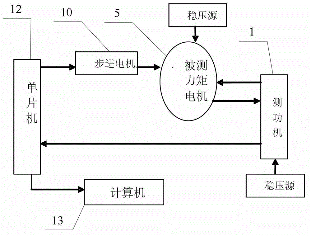
[0041] Specific implementation mode three: the following combination Figure 1 to Figure 3 Describe this embodiment, this embodiment is based on the detection method of the torque motor torque fluctuation coefficient detector described in Embodiment 1 or 2, and it comprises the following steps:

[0042] Step 1: Initially calibrate the dynamometer 1 using a calibration assembly consisting of a calibration lever 2 and a weight 3;

[0043] Step 2: Adjust the chuck manipulator 6 so that it firmly clamps the stator of the torque motor 5 under test;

[0044]Step 3: Power up the measured torque motor 5 to generate torque, and make the working voltage of the measured torque motor 5 continuously adjustable under the condition of not higher than the rated voltage of the motor; at the same time, the dynamometer 1 The current torque of 5 adds corresponding reverse torque to it, so that the measured torque motor 5 stops rotating; the continuous peak stall time of the measured torque motor...


PUM


Abstract

The invention relates to a torque motor torque fluctuation coefficient detector and a detecting method and belongs to the technical field of torque motor torque fluctuation measurement. The torque motor torque fluctuation coefficient detector and the detecting method solve the problems that during the process of measuring force from a stator to a sensor, existing torque motor torque fluctuation coefficient detectors are unreliable in detected results due to gravity interference of the stator. The detector comprises a dynamometer, a calibration assembly, a first coupler, a torque motor to be measured, a chuck mechanical arm, a load bearing, a second coupler, a position adjusting base, a stepping motor, a stabilizing base, a singlechip and a computer. The detecting method comprises the steps of firstly performing initial calibration; then adjusting the chuck mechanical arm to firmly clamp a stator of the torque motor to be measured; powering up the torque motor to be measured to enable the torque motor to be measured to generate torque, then enabling the torque motor to be measured to be under a lock rotor state; and finally driving the stator of the torque motor to be measured by the stepping motor to rotate a circle, synchronously collecting torque signals, and outputting the torque signals to the computer. The torque motor torque fluctuation coefficient detector and the detecting method are suitable for detection of torque motor torque fluctuation coefficients.

Description

technical field [0001] The invention relates to a torque motor torque fluctuation coefficient detector and a detection method, belonging to the technical field of torque motor torque fluctuation measurement. Background technique [0002] With the progress and development of modern science and technology, torque motors have been widely used in many fields such as machinery manufacturing, automatic control, aerospace and national defense. The practice of production and scientific research requires that the torque motor has high reliability, stability, controllability, energy saving and environmental protection. In terms of smooth operation, the torque fluctuation of the motor is required to be small. Therefore, in the detection process of the torque fluctuation of the motor, How to improve the practicability and reliability of detection tools is a very critical issue. [0003] At present, traditional dynamometers are still widely used in my country to test the performance of ...

Claims


Application Information

Patent Timeline
Patent Type & Authority Applications(China)
IPC IPC(8): G01L3/00
Inventor 关宇东杜克揭军仲小挺提纯利滕艺丹黄博闻陈家鑫李尔佳戴翊轩
Owner HARBIN INST OF TECH
Why Eureka
Try Eureka