Composite magnetic core structure and magnetic element

A technology of magnetic components and magnetic cores, applied in the field of composite magnetics, can solve the problems of inability to achieve the best use effect of magnetic components, increase in total loss of magnetic components, increase in magnetic core loss, etc., and achieve good electromagnetic interference EMI characteristics and magnetic core loss. The effect of reducing and reducing electromagnetic interference

Active Publication Date: 2013-03-06
XFUSION DIGITAL TECH CO LTD
View PDF3 Cites 40 Cited by
  • Summary
  • Abstract
  • Description
  • Claims
  • Application Information

AI Technical Summary

Problems solved by technology

In the traditional magnetic element design, we should consider using a single magnetic core material for the design of the magnetic element, which will inevitably bring a bottleneck to the design of the magnetic element and cannot achieve the best use of the magnetic element. Therefore, composite magnetic Technology should be born, using the composite of different magnetic cores, or the mixed processing and integral molding of different magnetic materials, will improve the overall performance of magnetic components
[0003] With the development of composite magnetic technology in the current industry, composite magnetic technology will receive more and more attention, and composite magnetic design technology will become necessary, but the inventor found that the composite magnetic core structure of most magnetic elements is in the process of realizing the embodiment of the present invention In order to avoid the increase of winding loss due to the air gap, the setting of the air gap is cancelled. However, although it reduces the winding loss, it will lead to an increase in the core loss, thereby increasing the total loss of the magnetic components, and the application frequency lower

Method used


Image

  • Composite magnetic core structure and magnetic element
  • Composite magnetic core structure and magnetic element
  • Composite magnetic core structure and magnetic element

Examples


Embodiment 1

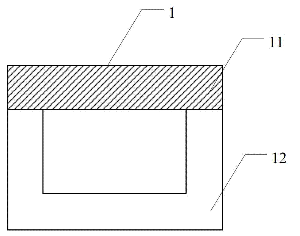
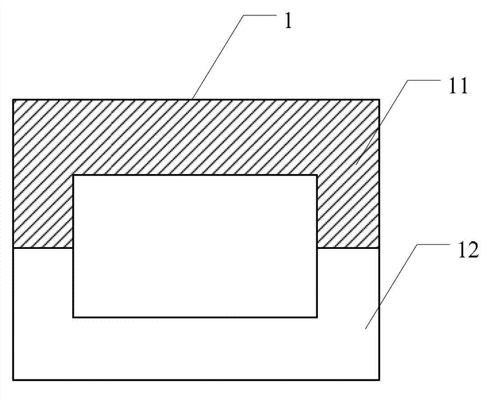
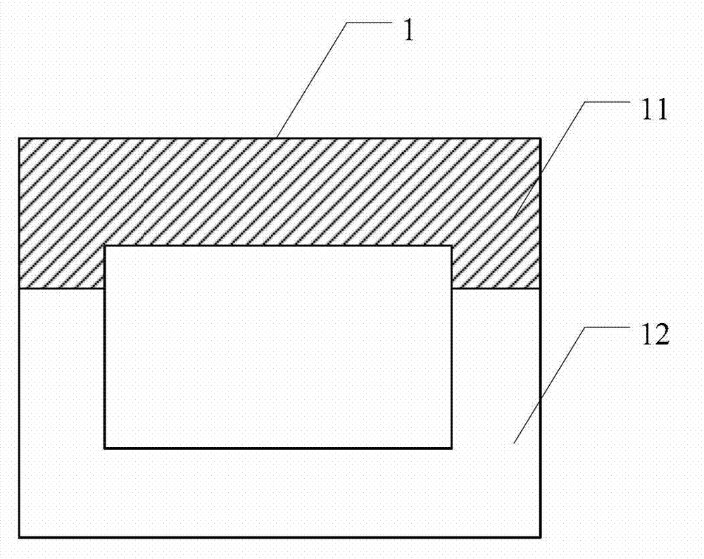
[0034] Please refer to figure 1 , figure 1 A schematic diagram of a composite magnetic core structure 1 provided by an embodiment of the present invention, wherein the composite magnetic core structure 1 includes:

[0035] The first magnetic core part 11 and the second magnetic core part 12, the first magnetic core part 11 is made of soft magnetic material with low magnetic permeability, and the second magnetic core part 12 is made of soft magnetic material with high magnetic permeability material, the first magnetic core part 11 and the second magnetic core part 12 are combined and form a magnetic flux circuit.

[0036] In the embodiment of the present invention, the soft magnetic material with low magnetic permeability is combined with the soft magnetic material with high magnetic permeability to form a magnetic flux circuit, that is, the composite magnetic core structure 1 is made of soft magnetic material with low magnetic permeability The first magnetic core part 11 and...

Embodiment 2

[0041] Preferably, this embodiment provides as figure 1 The shown composite magnetic core structure 1 is arranged in a UI shape; the shown UI-shaped composite magnetic core structure 1 includes an I-shaped set of magnetic core components and a U-shaped set of magnetic core components, wherein the I-shaped set of magnetic cores The component is a first magnetic core component 11 made of a soft magnetic material with low magnetic permeability, and the magnetic core component of the U-shaped arrangement is a second magnetic core component 12 made of a soft magnetic material with high magnetic permeability, The first magnetic core part 11 and the second magnetic core part 12 are combined to form a UI type composite magnetic circuit core;

[0042] Further, the soft magnetic material with low magnetic permeability constituting the first magnetic core part 11 can be one or more of other low magnetic permeability magnetic core materials such as nickel-zinc NiZn ferrite, alloy magnetic...

Embodiment 3

[0055] Please refer to Figure 5 , Figure 5 Another structural schematic diagram of a composite magnetic core structure 1 provided by an embodiment of the present invention, wherein the composite magnetic core structure 1 is arranged in an EI type, and the shown EI type composite magnetic core structure 1 includes:

[0056] The magnetic core part of the I-type setting and the magnetic core part of the E-type setting, wherein, the magnetic core part of the I-type setting is the first magnetic core part 11 made of a soft magnetic material with low magnetic permeability, and the E The magnetic core part of the type setting is the second magnetic core part 12 made of soft magnetic material with high magnetic permeability, and the first magnetic core part 11 and the second magnetic core part 12 are combined to form a UI type composite magnetic circuit magnetic core;

[0057] Further, the soft magnetic material with low magnetic permeability constituting the first magnetic core p...


PUM


Abstract

The embodiment of the invention discloses a composite magnetic core structure and a magnetic element, which are used for reducing magnetic core loss and increasing the frequency of application. In the embodiment of the invention, the composite magnetic core structure consists of a first magnetic core part and a second magnetic core part, the first magnetic core part is made of low-magnetic permeability soft magnetic material, the second magnetic core part is made of high-magnetic permeability soft magnetic material, and the first magnetic core part and the second magnetic core part are combined and formed into a magnetic flux loop.

Description

technical field [0001] The invention relates to the field of composite magnetic technology, in particular to a composite magnetic core structure and a magnetic element. Background technique [0002] In switching power supplies, magnetic components (or magnetic components) are the core components of energy conversion and storage, and their performance is related to the efficiency and performance of the entire switching power supply. As one of the main loss devices, magnetic components are increasingly subject to hardware design. The attention of personnel, and the magnetic core as the core component of the magnetic element, its performance is related to the performance of the magnetic element. How to reduce the loss of the magnetic element and improve the efficiency and overall performance of the switching power supply becomes the key. At the same time, the cost It is also an important factor to consider when designing the core structure. In the traditional magnetic element ...

Claims


Application Information

Patent Timeline
Patent Type & Authority Applications(China)
IPC IPC(8): H01F27/24H01F1/34H01F27/30
Inventor 孙永杰朱勇发杨和钱
Owner XFUSION DIGITAL TECH CO LTD
Why Eureka
Try Eureka