Energy recovery device based on vacuum flywheel energy storage and energy recovery method thereof

An energy recovery device and flywheel energy storage technology, applied in the direction of AC network load balancing, etc., can solve the problems of low energy density, high consistency requirements, and limited capacity of capacitor monomers, achieving high efficiency and high braking energy feedback Effect

Active Publication Date: 2013-03-06
江苏交科能源科技发展有限公司 +1
View PDF4 Cites 23 Cited by
  • Summary
  • Abstract
  • Description
  • Claims
  • Application Information

AI Technical Summary

Problems solved by technology

The method of feeding AC power back to the grid requires that there is a load in the range of the same transformer near the feedback device when feeding back power, otherwise this part of the fed back energy will have a certain impact on the grid, and through the bidirectional DC / DC converter and the use of capacitors The method of energy storage also has great disadvantages, because the capacity of a single capacitor is limited and the energy density is small, so a system with practical application value often requires thousands of capacitors to be connected in series and parallel to form an energy storage unit, and the quality generally reaches At the same time, there is a high requirement for the consistency of the capacitor monomer. However, the failure of a small amount of capacitors will still cause the abnormal operation of the entire system. Therefore, this method is mostly used in occasions with small loads, such as vertical elevators, etc.

Method used


Image

  • Energy recovery device based on vacuum flywheel energy storage and energy recovery method thereof

Examples


Embodiment

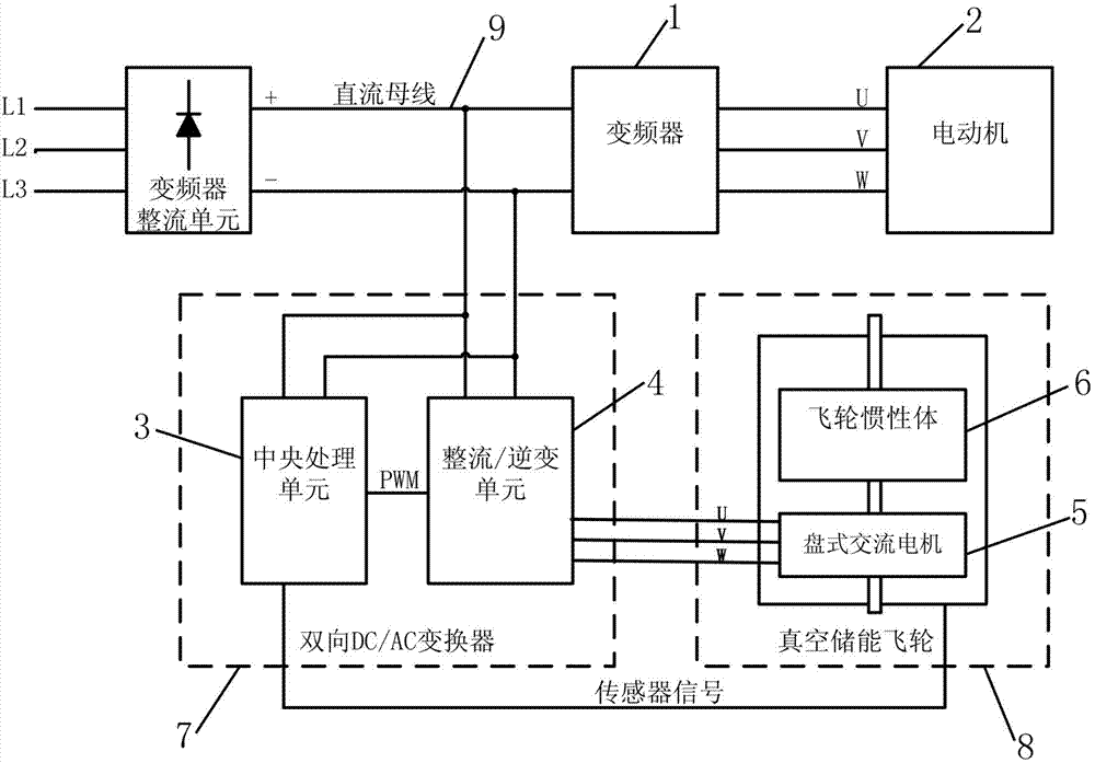
[0045] Reference figure 1 Take the port crane lifting unit as an example. After the port crane power supply is powered on, the grid 380V three-phase AC power is rectified into the DC bus of the variable frequency system. The DC bus voltage of the variable frequency system is 540V (peak value), and the braking unit starts the energy consumption resistance voltage threshold It is 700V, the minimum load speed of the vacuum energy storage flywheel is 5000rpm, the maximum load speed is 8000rpm, the upper limit monitoring threshold of the bidirectional DC / AC converter bus voltage is 680V, ​​and the lower limit monitoring threshold is 600V.

[0046] When the DC bus of the frequency conversion system is powered (powered by the grid), the energy recovery device starts to stand by. When the crane is not working, the bus voltage is 540V, the speed of the vacuum energy storage flywheel is zero, and the energy recovery device is still in standby; when the crane starts When the hook starts to ...


PUM


Abstract

The invention relates to an energy recovery device used for a variable frequency system of a motor, in particular to an energy recovery device for carrying out dynamic equilibrium on DC (direct current) bus voltage of the variable frequency system and an energy recovery method thereof. The energy recovery device comprises a bi-directional DC / AC (alternating current) converter and a vacuum energy storage flywheel, wherein the bi-directional DC / AC converter is respectively connected with a DC bus of the variable frequency system and the vacuum energy storage flywheel; the bi-directional DC / AC converter comprises a central processing unit, a rectification / inversion unit and periphery auxiliary circuits; and the central processing unit comprises a microprocessor, a circuit for acquiring the DC bus voltage and a circuit for acquiring rotating speed of the vacuum energy storage flywheel. The energy recovery method is characterized in that when the difference between the DC bus voltage of the variable frequency system and a preset upper limit threshold is monitored by the central processing unit, the rotating speed of the vacuum energy storage flywheel is monitored at the same time, so that whether a DC-AC flow is started or not is determined so as to enable the vacuum energy storage flywheel to absorb or release energy from the DC bus of the variable frequency system.

Description

technical field [0001] The invention relates to an energy recovery device for a frequency conversion system of a motor, in particular to an energy recovery device and an energy recovery method for dynamically balancing the DC bus voltage of the frequency conversion system. Background technique [0002] The motor drive system driven by the frequency converter will generate a large amount of braking energy when braking the motor, and this energy will be sent to the DC bus of the frequency converter. When the energy is too much, the bus voltage will increase excessively, which is To protect the frequency converter, the excess energy must be consumed by the braking unit through the energy consumption resistor. In order to recover this part of energy, a bidirectional converter can be used to convert the DC on the bus to AC and feed it back into the power grid. This part of the energy can also be used to charge the supercapacitor through a bidirectional DC / DC converter, and then p...

Claims


Application Information

Patent Timeline
Patent Type & Authority Applications(China)
IPC IPC(8): H02J3/30
CPCY02E60/16
Inventor 王勤施刚施增伟
Owner 江苏交科能源科技发展有限公司
Why Eureka
Try Eureka