
Boost integrated circuit for tuner

An integrated circuit and circuit technology, applied in the direction of conversion equipment without intermediate conversion to AC, can solve the problems of complex structure, high circuit implementation cost, high device precision, and high requirements for anti-interference parameters, and achieve the effect of strong flexibility

Inactive Publication Date: 2013-03-06
TENA ELECTRONICS
View PDF1 Cites 9 Cited by
  • Summary
  • Abstract
  • Description
  • Claims
  • Application Information

AI Technical Summary

Problems solved by technology

Therefore, the implementation cost of the circuit using this solution is high, and because this implementation method needs to occupy motherboard resources, this implementation method has basically been eliminated at present
[0005] Second, the tuner has its own +33V power supply, and this also requires an additional boost circuit inside the tuner
At present, more than ten devices such as transistors and inductors are mainly used to form an oscillating boost circuit. The structure of this circuit is complex and the failure rate is high. Since the oscillation generated by the boost circuit will cause interference to the tuned signal, it is necessary to realize the solution. The method has high requirements on the accuracy and anti-interference parameters of the device, and the cost of the device is high

Method used


Image

  • Boost integrated circuit for tuner
  • Boost integrated circuit for tuner
  • Boost integrated circuit for tuner

Examples


Embodiment 1

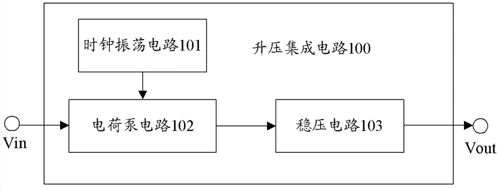
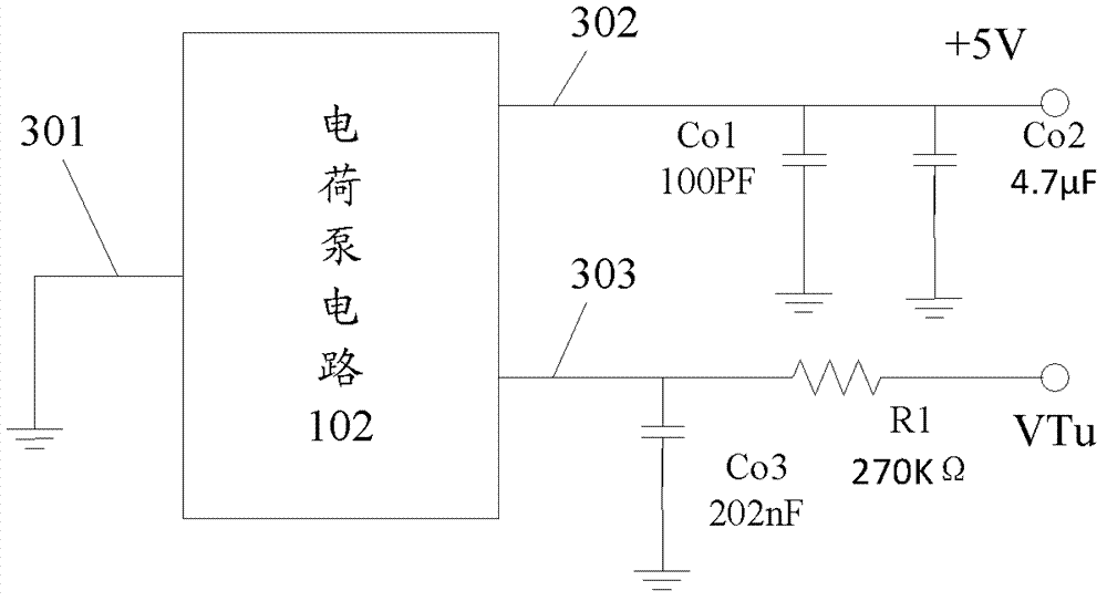
[0042] see Figure 1-3 As shown, a boost integrated circuit 100 provided in this embodiment mainly includes the following three parts: a clock oscillation circuit 101 , a charge pump circuit 102 , and a voltage stabilizing circuit 103 .

[0043] Wherein the clock oscillating circuit 101 is electrically connected with the charge pump circuit 102, the clock oscillating circuit 101 is used to provide the clock frequency signal for the charge pump circuit 102, the input end of the low noise circuit is externally connected with an external input low-voltage signal, and the output end is electrically connected to the voltage stabilizing circuit 103 connect.

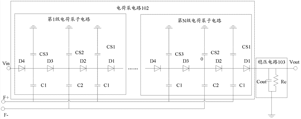
[0044] Wherein, the charge pump circuit 102 is composed of N stages of sequentially cascaded charge pump sub-circuits and an output load circuit, where N is a natural number, such as 1, 2, 3...N.

[0045] The charge pump sub-circuits at all levels are respectively composed of the first zener diode D1, the second zener diode D2...


PUM

PropertyMeasurementUnit
Granularityaaaaaaaaaa
Capacitanceaaaaaaaaaa

Abstract

The invention relates to the field of electrical design and discloses a boost integrated circuit for a tuner. The boost integrated circuit comprises a clock oscillation circuit, a charge pump circuit and a voltage stabilizing circuit, wherein the clock oscillation circuit is electrically connected with the charge pump circuit and used for providing clock frequency signals for the charge pump circuit. An input end of a low-noise circuit is externally connected with externally input low-voltage signals, and an output end of the low-noise circuit. The charge pump circuit comprises N levels of charge pump subcircuits and output load circuits in cascade connection, wherein the N is a natural number. By the above technical scheme, low-voltage electric signals can be boosted to required high-voltage electric signals, and the boost integrated circuit for the tuner is high in adaptability and adjustability according to practical application.

Description

technical field [0001] The invention relates to the field of electrical design, in particular to a boosting integrated circuit. Background technique [0002] The tuner is called Tuner in English. It is a device that completes the process of receiving, gating, frequency conversion, and demodulation in an analog way. It is commonly called a high-frequency head in TV sets. application. Such as M / AM tuner or TV tuner, both FM and AM are signal modulation methods, FM refers to frequency modulation, and AM refers to amplitude modulation. [0003] The current tuner needs a +33V voltage to work. At present, there are two ways to provide the tuning working voltage: [0004] One is that the main board provides the tuning working voltage electrical signal, and most of the main boards currently use low voltage (such as +5V) for power supply, so it is necessary to set a general boost circuit during implementation, through which the low voltage power supply The signal (eg +5V) is boost...

Claims


Application Information

Patent Timeline
IPC IPC(8): H02M3/07
Inventor 张向东
Owner TENA ELECTRONICS
Learn More