Pipeline facing machine

A technology of pipe beveling machine and casing, which is applied in the direction of metal processing machinery parts, clamping, support, etc., which can solve the problems of insufficient equipment strength, high manual labor intensity, falling and breaking of the machine, etc., and achieve an increase in volume-to-power ratio , Reduce labor intensity, strong and continuous effect

Inactive Publication Date: 2013-03-13
上海油威液压成套设备有限公司
View PDF3 Cites 10 Cited by
  • Summary
  • Abstract
  • Description
  • Claims
  • Application Information

AI Technical Summary

Problems solved by technology

[0007] 2. The machine is relatively small, but the pursuit of smallness is too small, resulting in insufficient strength of the equipment itself, high failure rate, and extremely low life span, which basically will not exceed half a year
Also because it is too small, the processing range of the machine is limited, resulting in a wide variety of machine models, as many as 5-6 specifications and models within the range of diameter 150mm~800mm
[0008] 3. High labor intensity
Large foreign equipment has a split type, that is, the machine is disassembled and assembled on the pipeline, but it is also very cumbersome and labor-intensive
[000...

Method used


Image

  • Pipeline facing machine
  • Pipeline facing machine
  • Pipeline facing machine

Examples


Embodiment 1

[0053] The present invention will be described below with reference to the accompanying drawings.

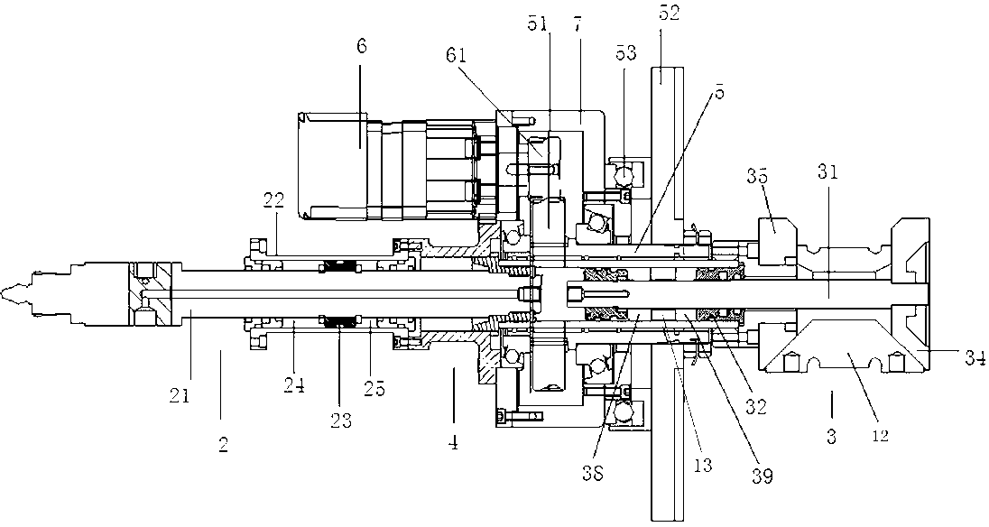
[0054] Insert the hydraulic tightening and braking device of the hydraulic tensioning device 3 into the pipeline 8, inject pressure oil into the fourth chamber 38, the seal 33 moves toward the hydraulic cutting and feeding device, and tighten the main shaft (piston rod) 31 at the same time Move toward the hydraulic cutting feeding device direction, because the pull block 34 is fixed on the tensioning main shaft 31, the pull block 34 moves toward the support block 35 direction, and at this moment, the inclined block 12 moves along the pull block 34 and the support block 35. The chute protrudes outward until the surface of the inclined block 12 (or the claw installed on the inclined block) contacts and expands the inner wall of the pipe 8. After the inclined block 12 is expanded, the pipe beveling machine is fixed on the end surface of the pipe 8 Above, after the pipe beveling mac...

Embodiment 2

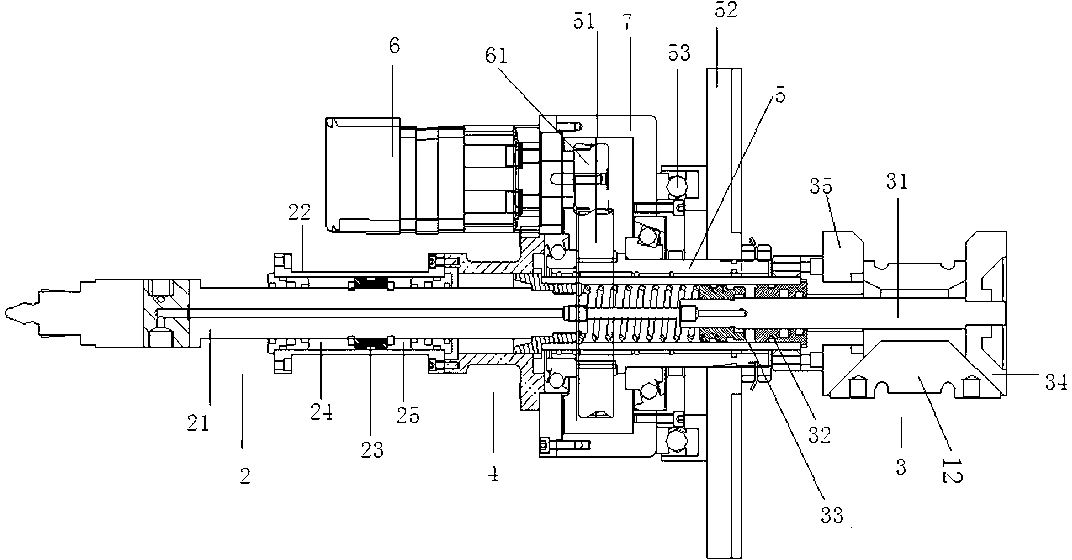
[0056] See attached below figure 2 The present invention is described with reference to the drawings.

[0057] Insert the hydraulic tensioning brake device of the hydraulic tensioning device 3 into the pipeline 8, inject the pressure oil into the fifth chamber 36, the seal 33 moves towards the hydraulic cutting feeding device, and the main shaft 31 is tightened to feed the hydraulic cutting at the same time Move in the device direction, because the pull block 34 is fixed on the tension main shaft 31, the pull block 34 moves toward the support block 35 direction, at this moment, the inclined block 12 stretches out along the chute on the pull block 34 and the support block 35 until the surface of the inclined block 12 is in contact with the inner wall of the pipe 8 and tightened, the pipe beveling machine is fixed on the end face of the pipe 8 after the inclined block 12 is expanded, and the driving device 6 works after the pipe beveling machine and the pipe are fixed. The pow...


PUM


Abstract

The invention relates to a pipeline facing machine, which comprises a main supporting shaft and an enclosure, wherein the main supporting shaft is provided with a main shaft sleeve; the main shaft sleeve is movably connected with the main supporting shaft via a bearing; the main shaft sleeve is provided with a transmission gear and a cutterhead; a hydraulic cutting and feeding device and a hydraulic expansion device are respectively arranged on two ends of the main supporting shaft; a driving device is meshed with the transmission gear via a power output gear; the driving device is fixedly arranged on the enclosure; and the enclosure is movably connected with the main shaft sleeve via a main enclosure supporting bearing. According to the pipeline facing machine disclosed by the invention, the facing machine and the a pipeline can be fixed and the cutterhead can be fed and retracted by the hydraulic expansion device and the hydraulic cutting and feeding device, the automatic degree and the manpower labor intensity are improved, and the pipeline facing machine has the advantages of high expansion speed, big expansion force, stability in feeding, compact equipment structure, small volumesize, wide pipeline applicable range and convenience in carrying. According to a proper device, one person can easily finish installing and disassembling the machine on the pipeline.

Description

technical field [0001] The invention relates to a metal pipeline welding auxiliary machine, which is a pretreatment equipment before pipeline welding. The main function is to make pipeline slopes with different angles and shapes on the pipeline by using blades of different shapes and angles according to the welding requirements of different pipelines. mouth machine. Background technique [0002] In the construction process of petroleum, chemical, natural gas, metallurgy, steel, pharmaceutical and other industries, metal pipes of different materials are required. Pipe connections are basically done by welding. If welding is required, welding grooves are required. [0003] In the past construction, flame cutting was mainly used for welding grooves, but after flame cutting, it will affect the change of metal microstructure at the cutting place and seriously affect the welding quality. Therefore, cold cutting is generally required in some occasions with medium and high req...

Claims


Application Information

Patent Timeline
IPC IPC(8): B23D79/00B23Q3/00B23Q5/32B23Q5/26
Inventor 杨浩
Owner 上海油威液压成套设备有限公司
Why Eureka
Try Eureka