

Distributed optical fiber temperature measuring device for real-time calibration and calibration method
A technology of distributed optical fiber and temperature measurement device, which is applied in measurement devices, thermometer testing/calibration, thermometers with physical/chemical changes, etc., can solve problems such as measurement errors, achieve strong operability, eliminate measurement errors, and structure simple effect
- Summary
- Abstract
- Description
- Claims
- Application Information
AI Technical Summary
Problems solved by technology
Method used
Image

Examples
Embodiment 1
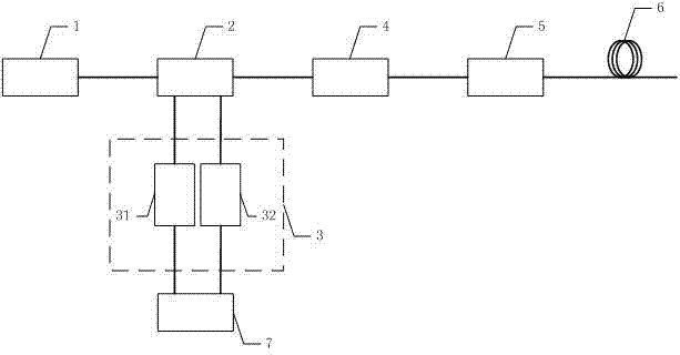
[0025] Such as figure 1 As shown, a real-time calibrated distributed optical fiber temperature measurement device includes a pulsed laser source 1 , a beam splitter 2 , a detector 3 , a reference fiber box 4 , a calibration fiber box 5 , a measuring fiber 6 and a circuit module 7 . The output end of the pulse light source 1 is connected with the input end of the optical splitter 2, and the first output end of the optical splitter 2 is connected with the reference fiber box 4, the calibration optical fiber box 5, and the measuring fiber 6 in turn, and the second output end of the optical splitter 2 is connected with the second output end of the optical splitter 2. The three output ends are connected to the input end of the detector 3 , and the output end of the detector 3 is connected to the circuit module 7 .
[0026] The pulsed light source 1 is a semiconductor laser light source or a fiber laser light source with narrow pulse width and high peak power. In this embodiment, a...
Embodiment 2
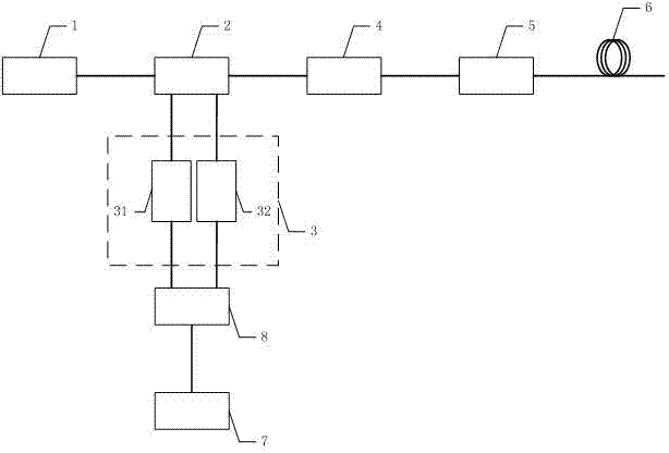
[0040] Such as image 3 As shown, a distributed optical fiber temperature measurement device with real-time calibration of a single detector, including a pulsed laser source 1, a beam splitter 2, a detector 3, a reference fiber box 4, a calibration fiber box 5, a measuring fiber 6, and a circuit module 7 and 1×2 optical switch 8. The difference from Embodiment 1 is that a 1×2 optical switch 8 is added between the beam splitter 2 and the detector 3, and the detector 3 is a single detector. The second output terminal and the third output terminal of the optical splitter 2 are respectively connected to the two input terminals of the 1×2 optical switch 8, and the output terminal of the 1×2 optical switch 8 is connected to the detector 3 The input terminals of the detector 3 are connected to each other, and the output terminals of the detector 3 are connected to the circuit module 7 .
[0041] The 1×2 optical switch 8 may be an optical switch with a MEMS structure or a mechanical...
PUM
| Property | Measurement | Unit |
|---|---|---|
| Center wavelength | aaaaa | aaaaa |
Abstract
Description
Claims
Application Information