
Submarine cable with increased current-carrying capacity

A submarine cable and flow technology, which is applied in the direction of submarine cables, power cables with shielding layers/conductive layers, etc., can solve problems such as poor seawater corrosion resistance, decreased current carrying capacity of cables, and weakened service life of aluminum wires, etc., to avoid Effects of partial discharge, increased carrying capacity, and low power loss

Inactive Publication Date: 2013-03-13
JIANGSU YUANYANG DONGZE CABLE
View PDF5 Cites 22 Cited by
  • Summary
  • Abstract
  • Description
  • Claims
  • Application Information

AI Technical Summary

Problems solved by technology

However, it uses steel-aluminum composite stranded wire as the conductor, and galvanized steel wire and aluminum alloy wire as the armor layer. Because aluminum has poor seawater corrosion resistance, long-term use will cause the aluminum wire to be corroded and reduce its service life, which will bring safety to use. Hidden dangers, especially the aluminum alloy wire in the armor will no longer have the magnetic isolation effect after corrosion and aging. At this time, the steel wire armor will generate eddy current loss on the single-core cable, resulting in a decrease in the current carrying capacity of the cable, which cannot reach the expected design carrying capacity.

Method used


Image

  • Submarine cable with increased current-carrying capacity
  • Submarine cable with increased current-carrying capacity

Examples


Embodiment Construction

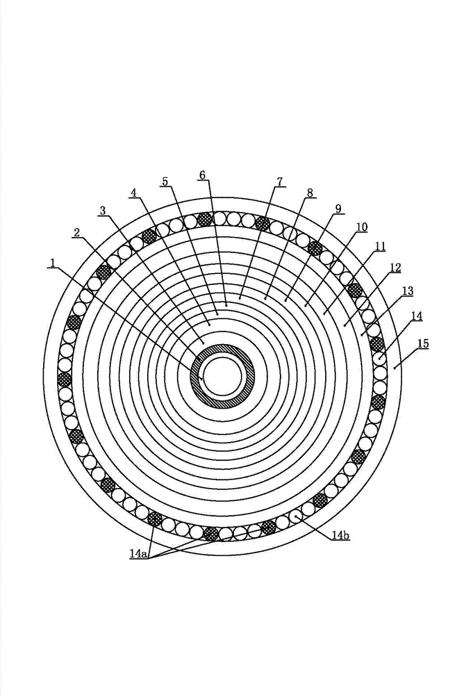
[0019] Such as figure 1 As shown, in a submarine cable with increased current carrying capacity of the present invention, the inner cavity of the tinned copper spiral tube 1 is provided with a hollow oil passage, and the aperture of the hollow oil passage is 18 mm; A highly conductive annealed annealed copper wire with a monofilament diameter of 2.57±0.03 mm constitutes the conductor layer 2 , and each highly conductive annealed annealed copper wire is spirally and closely arranged in a circular array on the outer periphery of the tinned copper spiral tube 1 .

[0020] The outer circumference of the conductor layer 2 is evenly wrapped with a carbon black paper conductor shielding layer 3, and the outer circumference of the carbon black paper conductor shielding layer 3 is evenly wrapped with an oil-filled high-voltage cable paper insulating layer 4. The thickness of the oil-filled high-voltage cable paper insulating layer 4 is 10±0.1mm. The outer circumference of the oil-fill...


PUM

PropertyMeasurementUnit
pore sizeaaaaaaaaaa
thicknessaaaaaaaaaa
diameteraaaaaaaaaa

Abstract

The invention relates to a submarine cable with an increased current-carrying capacity. Conductor layers comprising a plurality of annealed copper wires with high conductivity are tightly distributed at the periphery of a tin-plated copper spiral pipe; a carbon black paper conductor shielding layer, an oil-filled high-voltage cable paper insulating layer, a carbon black paper insulation shielding layer, a copper strip insulation shielding layer and a seamless lead-alloy sheath are wrapped at the periphery of the conductor layers sequentially; asphalt is evenly coated at the periphery of the seamless lead-alloy sheath; and a self-adhesive polyethylene strip inner cushion layer, double stainless steel strip strengthening layers, a self-adhesive polyethylene strip outer cushion layer, a non-woven fabric liner layer, a high-density polyethylene corrosion resisting layer, an armoured inner cushion layer formed by evenly soaking hemp ropes at intervals through polypropylene ropes in a concentric stranding manner, an armoured layer formed by uniform spacing of aluminum-magnesium-plated alloy steel wires and a copper wire in the concentric stranding manner and an outer protecting layer are wrapped at the periphery of the seamless lead-alloy sheath sequentially. The submarine cable has a larger current-carrying capacity and is excellent in water seepage resistance, seawater corrosion resistance, external water pressure resistance, voltage thermal shock resistance and tension bending resistance. In addition, the submarine cable also has the advantages of long service life and high reliability.

Description

technical field [0001] The invention relates to a power cable, in particular to a submarine cable with increased carrying capacity. Background technique [0002] With the development and utilization of marine energy, more and more submarine cables are used as current-carrying equipment for submarine electric energy transmission, and the technical requirements are getting higher and higher. In particular, cables are required to have excellent mechanical, physical and electrical properties, and have greater current-carrying capacity, Excellent anti-seepage, seawater corrosion resistance, external water pressure resistance, voltage thermal shock resistance and tensile bending resistance, long service life and high reliability. Submarine cables in the prior art pay more attention to seawater corrosion resistance, tensile mechanical properties and water seepage resistance, while ignoring the requirement for cables with greater ampacity. [0003] The Chinese utility model patent ...

Claims


Application Information

Patent Timeline
Patent Type & Authority Applications(China)
IPC IPC(8): H01B9/02H01B7/14
Inventor 李永江陆云春
Owner JIANGSU YUANYANG DONGZE CABLE
Learn More