
Video encoding unit and realizing method thereof

A video coding and video technology, applied in the field of video coding unit and its implementation, can solve the problems of small selection of front-end video interface chips, technical difficulty of soft coding method, and working state, and achieves efficient, reasonable, advanced, and dedicated design. Strong, reduced use effect

Active Publication Date: 2013-03-13
CHINESE AERONAUTICAL RADIO ELECTRONICS RES INST
View PDF4 Cites 18 Cited by
  • Summary
  • Abstract
  • Description
  • Claims
  • Application Information

AI Technical Summary

Problems solved by technology

[0003] The video encoding unit is the most critical part of the video recording system, because the quality of the video encoding performance directly determines the quality of the image, and indirectly affects the demand for data throughput of the internal bus of the video recording system and the capacity of the back-end storage medium Requirements, at present, most of the video coding standards adopt the H.264 / AVC standard formulated by the Joint Video Team (JVT) composed of ISO / IEC and ITU-T, and the standard can be realized in various ways, such as adopting on CPU or DSP It is realized by running video compression algorithm, which is often referred to as soft coding, or using FPGA (Field-Programmable Gate Array, Field Programmable Gate Array) chips to realize video coding processing by means of on-site programming, but the above methods are more or less At least there are some unavoidable defects. The soft coding method is technically difficult, the development threshold is high, the development cycle is long, and the selection of front-end video interface chips is small. However, the method of using FPGA chips can more flexibly realize the coding of multi-channel video. , but because the FPGA chip realizes the video encoding, the internal redundant unit is still in the working state, resulting in a large power consumption

Method used


Image

  • Video encoding unit and realizing method thereof
  • Video encoding unit and realizing method thereof
  • Video encoding unit and realizing method thereof

Examples


Embodiment Construction

[0017] The preferred embodiments of the present invention are given below in conjunction with the accompanying drawings to describe the technical solution of the present invention in detail.

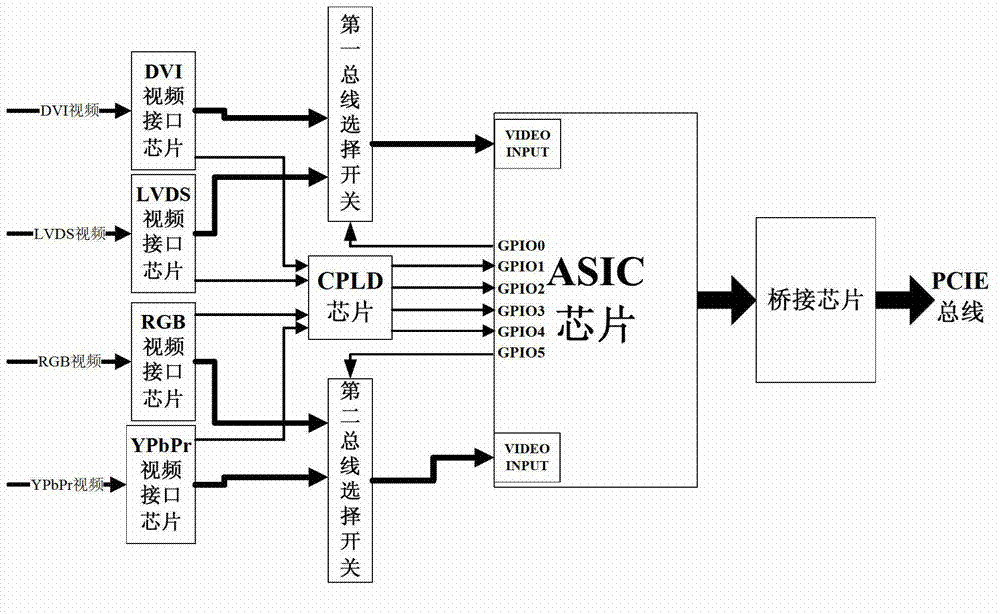
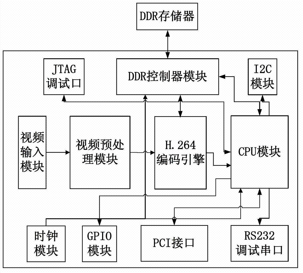
[0018] Such as figure 2 Shown, the video coding unit of the present invention comprises DVI video interface chip, LVDS video interface chip, RGB video interface chip, YPbPr video interface chip, the first bus selection switch, the second bus selection switch, CPLD (Complex Programmable Logic Device, complex programmable programming logic device) chip, ASIC (Application Specific Integrated Circuit, application specific integrated circuit) chip, bridge chip, DVI video interface chip, LVDS video interface chip are all connected to the first bus selection switch, DVI video interface chip, LVDS video interface chip, The RGB video interface chip and the YPbPr video interface chip are all connected to the CPLD chip, the RGB video interface chip and the YPbPr video interface chip are also conne...


PUM


Abstract

The invention discloses a video encoding unit and a realizing method thereof. The video encoding unit comprises a DVI (digital visual interface) chip and the like, wherein the DVI chip and an LVDS (low-voltage differential signaling) video interface chip are connected with a first bus selective switch, the DVI chip, the LVDS video interface chip, an RGB (red, green, blue) video interface chip and a YPbPr video interface chip are connected with a CPLD (complex programmable logic device) chip, the RGB video interface chip and the YPbPr video interface chip are connected with a second bus selective switch, the first bus selective switch, the second bus selective bus, the CPLD chip and an ASIC (application specific integrated circuit) chip, and the ASIC chip is connected with a bridge connection chip. The video encoding unit has the characteristics of easiness in development, low power consumption, high performance and the like, can totally meet requirements of a vehicle-mounted high-definition video recording system.

Description

technical field [0001] The present invention relates to a coding unit, in particular to a video coding unit and its implementation method. Background technique [0002] The video recording system is a device in the avionics system specially used to record the video screen of the aircraft cockpit display. It will record all the flight control screens during the flight into a non-volatile storage medium for ground analysis after the flight. , the video recording system is mainly composed of a video encoding unit, a main control unit, and a storage unit. The signal flow diagram is as follows figure 1 As shown, the video encoding unit receives multiple channels of high-definition video and encodes and compresses them, and sends the compressed code stream data to the main control unit through the PCIE bus. The main control unit is responsible for packaging the code stream data, file management, and finally sends stored in the storage unit. [0003] The video encoding unit is th...

Claims


Application Information

Patent Timeline
IPC IPC(8): H04N7/26H04N19/00
Inventor 章圣焰陈广水
Owner CHINESE AERONAUTICAL RADIO ELECTRONICS RES INST
Learn More