Electro-plastic friction stir spot welding device and method thereof

A technology of friction stir and electroplasticity, which is applied in the direction of non-electric welding equipment, welding equipment, metal processing equipment, etc., can solve the problems of weak connection surface, low interface temperature, virtual connection and holes, etc., to strengthen the inherently weak connection surface, Effects of improving forming temperature and environment and improving plastic flow ability

Inactive Publication Date: 2013-03-20
SHANGHAI DIANJI UNIV
View PDF9 Cites 7 Cited by
  • Summary
  • Abstract
  • Description
  • Claims
  • Application Information

AI Technical Summary

Problems solved by technology

[0004] During the friction stir spot welding process, when the stirring sleeve is pressed in, a new interface will be formed on the side wall of the outer ring of the joint, and during the backfilling process of the stirring pin, this interface will form a new connection with the thermoplastic material extruded and flowing there. However, due to the relatively low interface temperature and insufficient plastic flow capacity of the material, the forming conditions of the new joint surface are harsh, which easily leads to weak joint surfaces, and even defects such

Method used


Image

  • Electro-plastic friction stir spot welding device and method thereof
  • Electro-plastic friction stir spot welding device and method thereof

Examples


Embodiment Construction

[0019] Hereinafter, preferred embodiments of the present invention are given in conjunction with the drawings to illustrate the technical solutions of the present invention in detail.

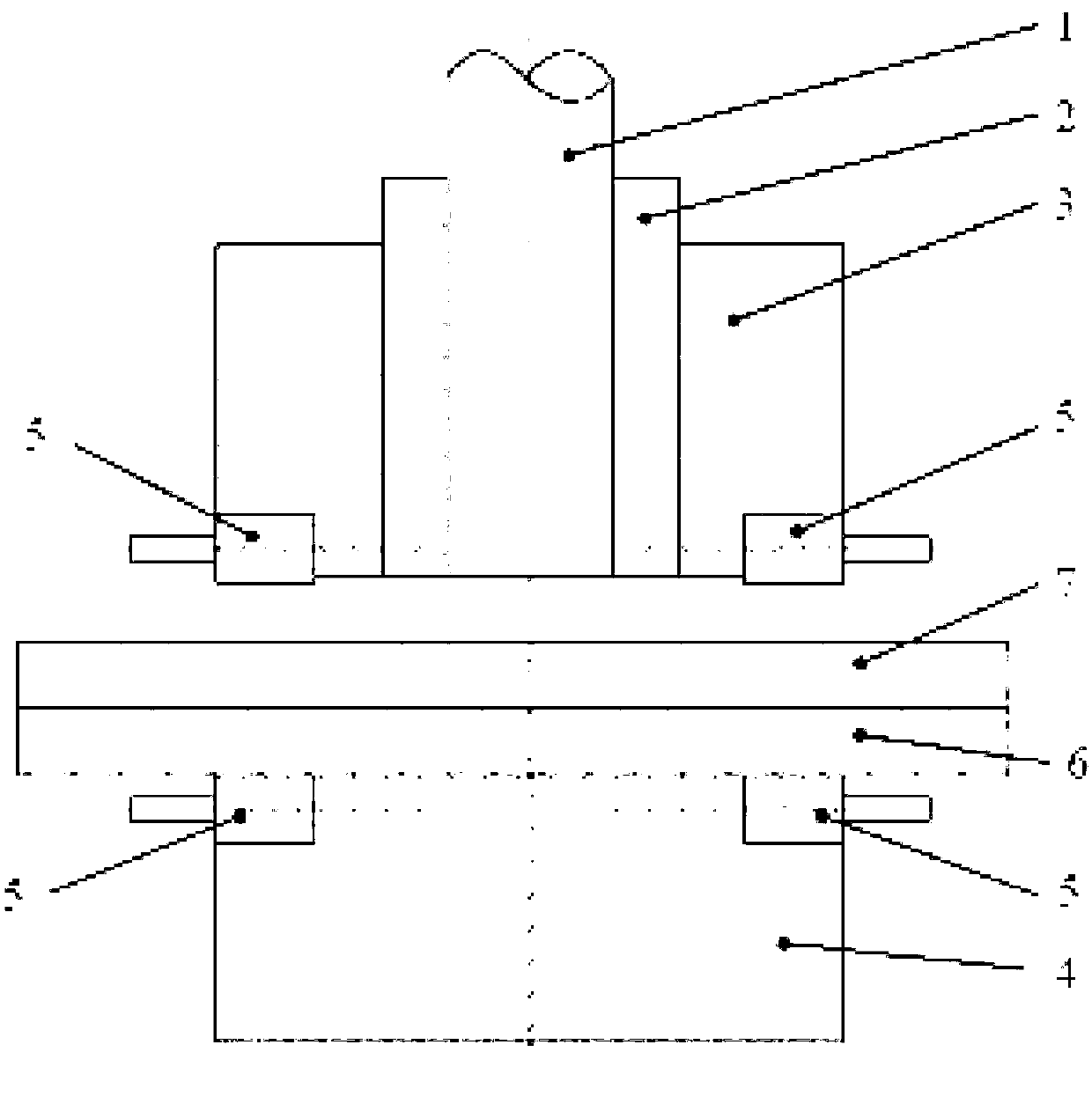
[0020] Such as figure 1 As shown, an electroplastic friction stir spot welding device of the present invention includes a stirring sleeve 2, a stirring needle 1 in the stirring sleeve, a clamping sleeve 3 clamped outside the stirring sleeve 2, and a welding pad 4 There is a welding workpiece between the clamping sleeve 3 and the welding pad 4, characterized in that the bottom of the clamping sleeve 3 and the top of the welding pad 4 are respectively provided with two radial opening grooves, and The brush 5 is installed in the groove, and the shape of the groove matches the shape of the conductive block in the brush 5.

[0021] Preferably, the clamping sleeve 3 and the welding pad 4 are made of insulating materials, or the surfaces are coated with insulating paint.

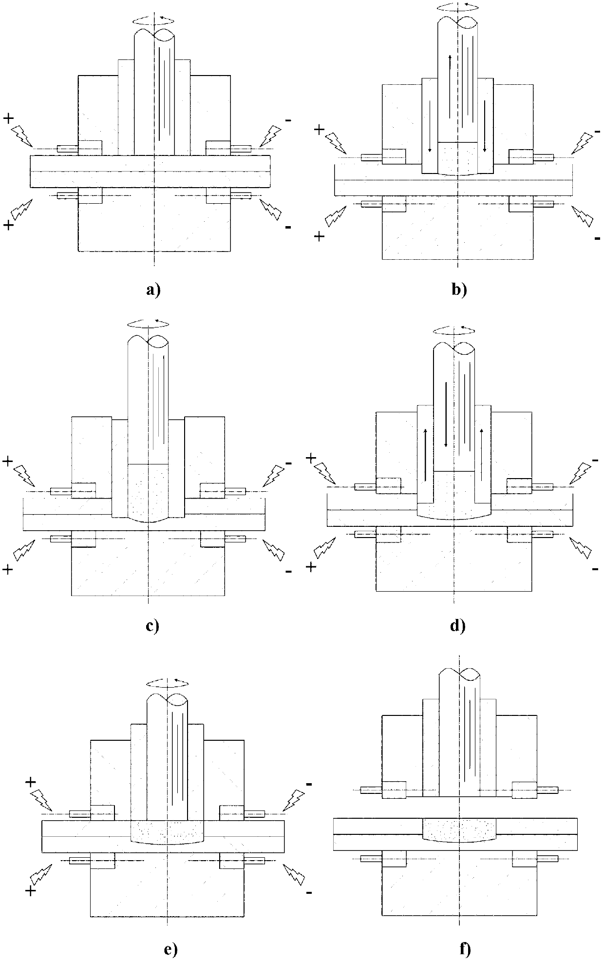
[0022] Such as figure 2 As shown...


PUM


Abstract

The invention provides an electro-plastic friction stir spot welding device, which comprises a stir sleeve, a stir needle in the stir sleeve, a clamping sleeve clamped outside the stir sleeve, and a welding cushion block, wherein two radial opening grooves are formed in the bottom of the clamping sleeve and the top of the welding cushion block respectively; electric brushes are mounted in the grooves; and the grooves are matched with the conductive blocks in the electric brushes in shape. The invention further provides an electro-plastic friction stir spot welding method, which comprises the steps of carrying out plastic softening on a metal material, communicating the two electric brushes with a direct current independently and respectively while compacting a welding workpiece by the clamping sleeve, enabling the polarities of the two electric brushes on the same horizontal plane to be opposite and the polarities of the two electric brushes on the same vertical plane to be the same, connecting a welding circuit, and finishing the welding operation by adopting a spot welding process. According to the invention, a high-density current is applied to the metal deformation direction by utilizing the electro-plastic effect of the metal material, so that the metal dislocation is promoted, the motion defect is overcome, the plastic flow capability of the metal material is improved, and the welding quality is improved.

Description

Technical field [0001] The invention relates to an electroplastic friction stir spot welding device and a method for performing spot stir welding using the device. Background technique [0002] Friction stir spot welding technology is a new type of solid phase connection technology, invented by the German GKSS Research Center in 1999. For details, see US Patent US6722556-B2. This technology uses a special stirring head composed of a stirring needle, a stirring sleeve and a clamping sleeve. By precisely controlling the relative movement of each part of the stirring head, the exit hole formed by the stirring head during the welding process is filled while the stirring head is retracted. Thereby forming a spot welded joint with a flat surface. [0003] Chinese patent CN102091860A discloses a double-acting ring friction spot welding method. This method changes the static clamping sleeve in the traditional friction stir spot welding into a rotating ring with a downward pressing action...

Claims


Application Information

Patent Timeline
IPC IPC(8): B23K28/00B23K20/12B23K20/26
Inventor 杨洪刚
Owner SHANGHAI DIANJI UNIV
Why Eureka
Try Eureka