Desulfurized ash delivery device

A conveying equipment and desulfurization ash technology, applied in the field of desulfurization ash conveying equipment and powder material pneumatic conveying equipment, can solve the problems of low fan outlet pressure, high back pressure, jamming, etc. The effect of high outlet pressure

Inactive Publication Date: 2013-03-20
ZHENJIANG CITY POWER STATION AUXILIARY MACHINERY PLANT
View PDF9 Cites 4 Cited by
  • Summary
  • Abstract
  • Description
  • Claims
  • Application Information

AI Technical Summary

Problems solved by technology

[0003] 1. Desulfurization ash is not easy to be smoothly transported to the reaction tower through the desulfurization ash conveying equipment;
[0004] 2. The fluidity of circulating desulfurization ash is poor during the process of being smoothly transported to the reaction tower through the desulfurization ash conveying equipment, resulting in "bridging", "bridging" and "jamming" of materials;
[0005] 3. In the process of the circulating desulfurization ash being successfully transported to the reaction tower through the desulfurization ash conveying equipment, the desulfurization ash is often not conveyed smoothly, and the material is not easy to be conveyed away
[0006] 4. When the circulating desulfurization ash is successfully transported to the reaction tower through the desulfurization ash conveying equipment, the flow and conveying of the desulfurized ash in the desulfurization ash conveying equipment should not be observed at any time
[0007] 5. The amount of desulfurized ash entering the reaction tower through the desulfurized ash conveying equipment is uncontrollable, which cannot meet the actual demand of the reaction tower for desulfurized ash
[0008] 6. The air source of the desulfurization ash conveying equipment adopts a centrifugal fan, but the back pressure is relatively high when the desulfurization ash is conveyed, and the outlet pressure of the fan is small, so the desulfurization ash cannot be conveyed smoothly

Method used


Image

  • Desulfurized ash delivery device
  • Desulfurized ash delivery device
  • Desulfurized ash delivery device

Examples


specific Embodiment approach

[0028] DETAILED DESCRIPTION OF THE PREFERRED EMBODIMENTS The present invention will be described in detail below in conjunction with the accompanying drawings

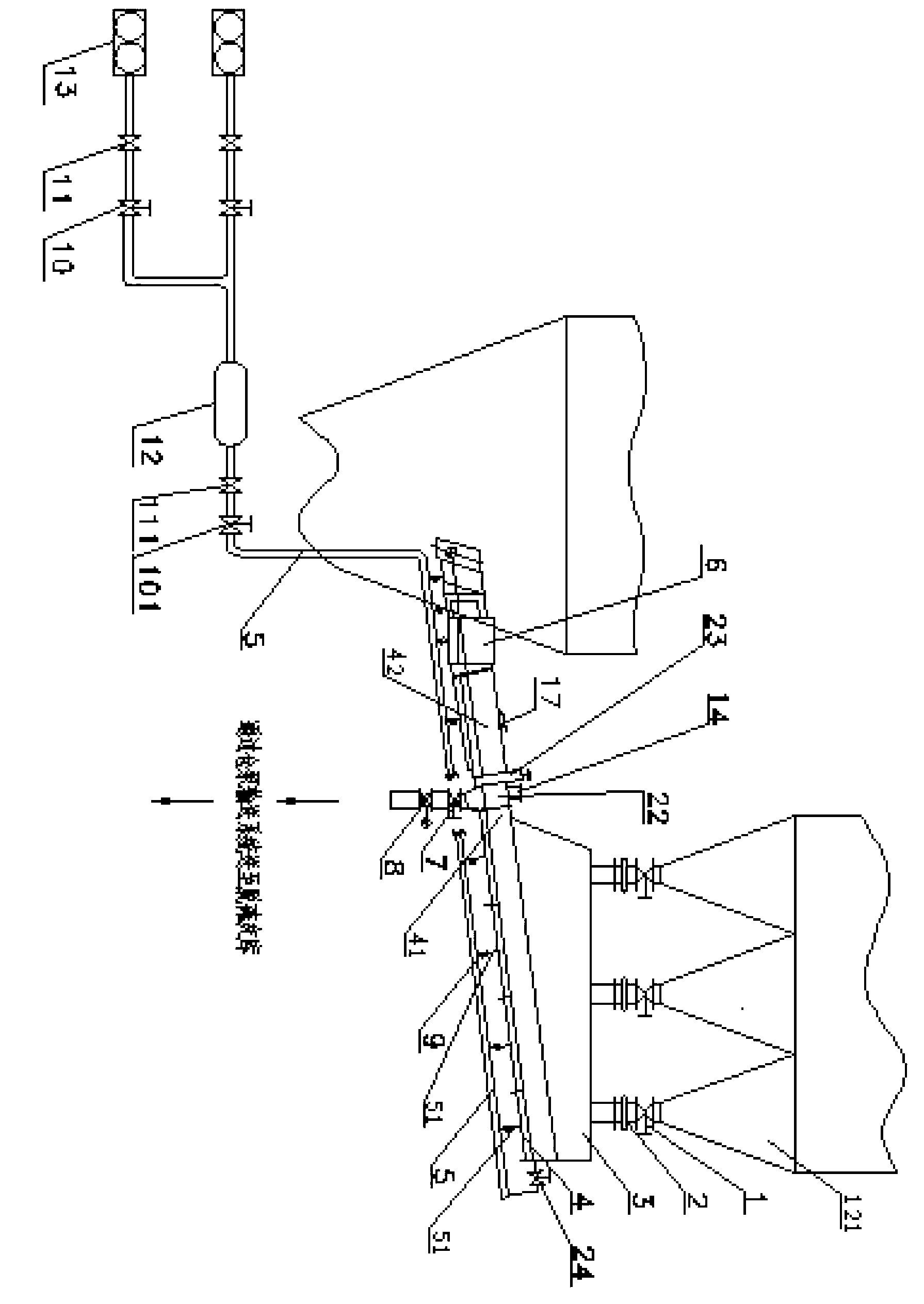
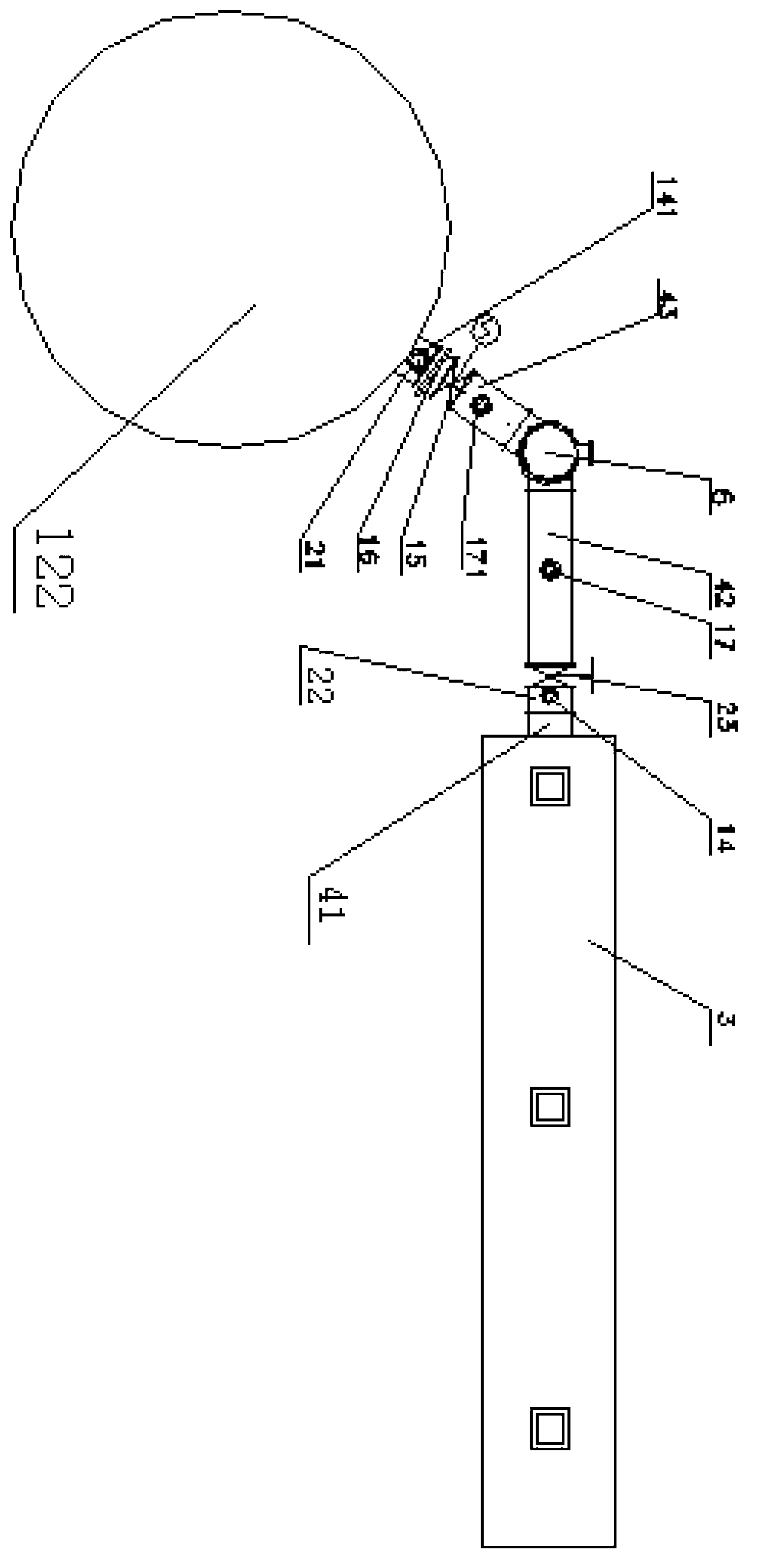
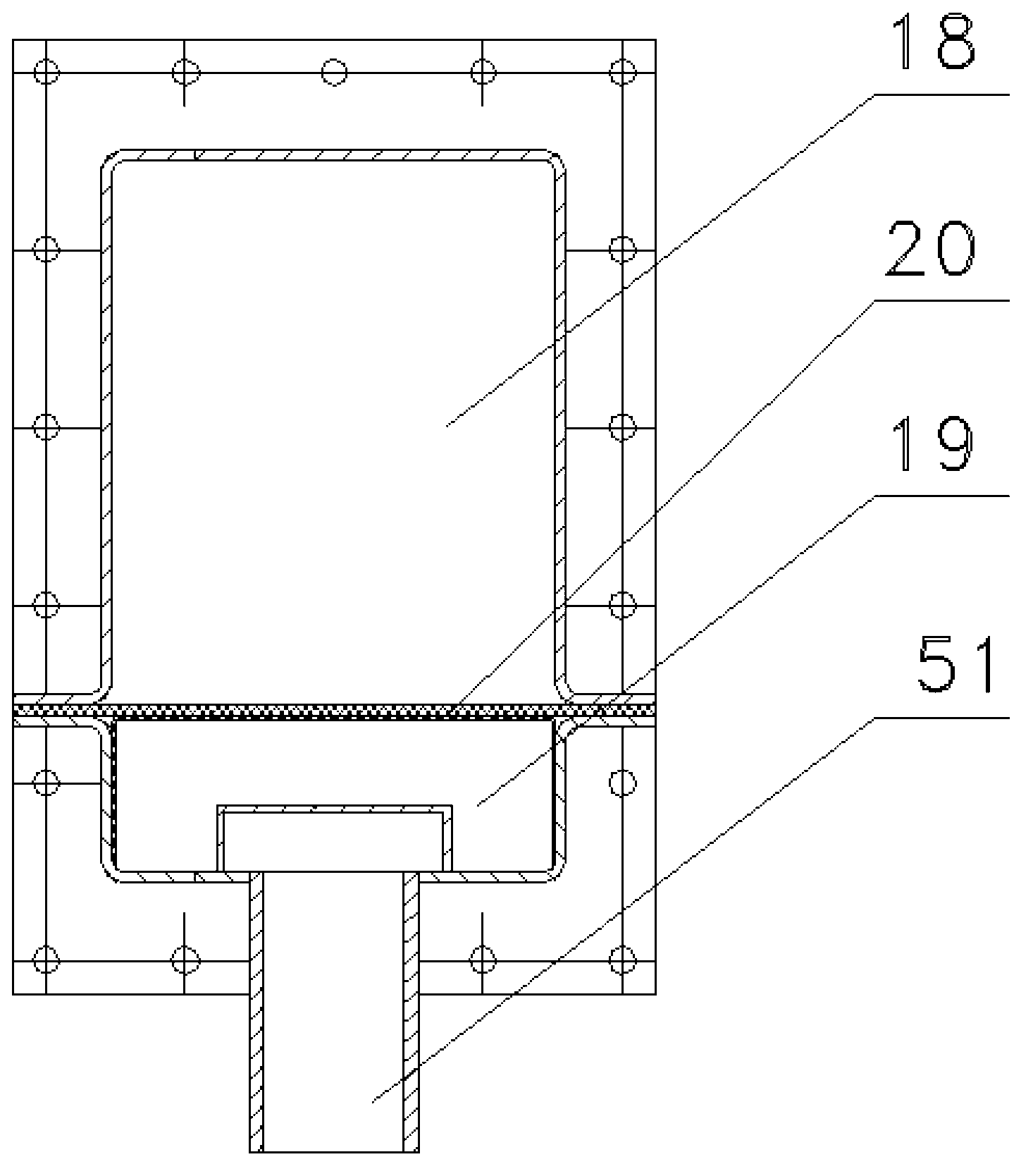
[0029] A desulfurization ash conveying equipment, including a plurality of ash hoppers 121 arranged under the secondary dust collector, each ash hopper 121 is connected with an on-off valve 1 and a first telescopic joint 2 in turn, and the first telescopic joint 2 is provided with The total ash hopper 3 is connected with an air supply pipe 5; the first telescopic joint 2 is connected with the total ash hopper 3, and the total ash hopper 3 is provided with a chute 4, which is inclined downward, and the chute One end of the groove 4 communicates with the total ash hopper 3, and a fluidized cloth 20, an air intake chamber 19, and an air intake pipe 51 are arranged between the chute 4 and the total ash hopper 3, and one end of the air intake pipe 51 communicates with the air intake chamber 19, and the other end communicates...


PUM


Abstract

The invention provides a desulfurized ash delivery device which comprises a general ash hopper arranged below a secondary dust remover. The general ash hopper is provided with a plurality of ash hoppers. Each ash hopper is connected with the general ash hopper through a switch valve and a first extensible node. The general ash hopper is connected with an air supply pipe and is provided with a chute. The chute is connected with a first ash delivery channel. The first ash delivery channel is connected with a middle connecting pipe. The middle connecting pipe is connected with a shutoff valve. A first exhaust gas opening is formed in the upper portion of the middle connecting pipe. The middle connecting pipe is connected with a feeding machine. The shutoff valve is connected with a second ash delivery channel. The second ash delivery channel is connected with a third ash delivery channel through a diverting device. The other end of the third ash delivery channel is sequentially connected with a second extensible node and a connecting pipe. A second exhaust gas opening is formed in the upper portion of the connecting pipe. The desulfurized ash delivery device is capable of delivering desulfurized ash smoothly to a rection tower and preventing phenomena of building bridge, erecting bridge and jam from occurring in the process of the desulfurized ash delivery.

Description

technical field [0001] The invention relates to a pneumatic conveying device for powdery materials, more specifically relates to a desulfurized ash conveying device, and belongs to the field of auxiliary equipment for circulating fluidized bed desulfurization. Background technique [0002] As my country controls and reduces SO 2 With the continuous increase of emissions, flue gas desulfurization has entered a stage of rapid development, and a desulfurization system is used; during the desulfurization process, the circulating desulfurization ash can be smoothly transported to the reaction tower through the desulfurization ash conveying equipment. However, the current desulfurization ash conveying equipment has the following disadvantages: [0003] 1. The desulfurization ash is not easy to be smoothly transported to the reaction tower through the desulfurization ash conveying equipment; [0004] 2. The fluidity of circulating desulfurization ash is poor during the process of...

Claims


Application Information

Patent Timeline
Patent Type & Authority Applications(China)
IPC IPC(8): B65G53/04B65G53/36B65G53/50B65G53/46
Inventor 虞永川张凯卿洪坤郑庆喜李叶凡虞瑞鹤瞿进詹胡琴马春花
Owner ZHENJIANG CITY POWER STATION AUXILIARY MACHINERY PLANT
Why Eureka
Try Eureka