SCS (structure cabling system) encased structure based on longitudinal stiffening ribs

A technology of steel tube concrete and concrete structures, which is applied in the direction of load-bearing elongated structural components, structural elements, building components, etc., which can solve the problems of small hoop effect, poor connection performance, self-heavy, etc., and achieve low construction cost , good torsion resistance, simple form

Inactive Publication Date: 2013-03-20
CHANGAN UNIV
View PDF6 Cites 9 Cited by
  • Summary
  • Abstract
  • Description
  • Claims
  • Application Information

AI Technical Summary

Problems solved by technology

[0005] The technical problem to be solved by the present invention is to provide a SCS steel pipe concrete structure based on longitudinal stiffeners, which is simple in structure, reasonable in design, convenient in construction, low in construction cost, excellent in mechanical properties, and easy to use in view of the above-mentioned deficiencies in the prior art. The effect is good, and it can effectively solve the problems existing in the existing steel pipe concrete structure, such as the self-heaviness, the poor connection performance between the outer steel pipe and the inner concrete, and the small hoop effect of the outer steel pipe on the inner concrete.

Method used


Image

  • SCS (structure cabling system) encased structure based on longitudinal stiffening ribs
  • SCS (structure cabling system) encased structure based on longitudinal stiffening ribs
  • SCS (structure cabling system) encased structure based on longitudinal stiffening ribs

Examples


Embodiment 1

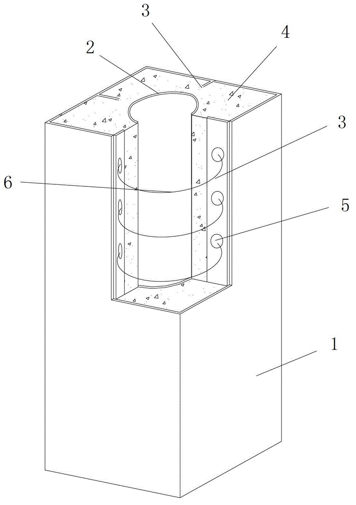
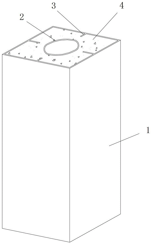
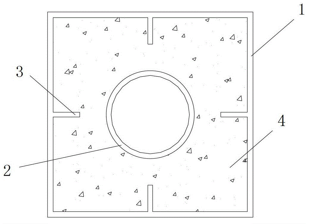
[0037] like figure 1 , figure 2 and image 3As shown, the present invention includes an outer steel pipe 1, an inner steel pipe 2 set inside the outer steel pipe 1, multiple longitudinal stiffeners 3 arranged on the inner wall of the outer steel pipe 1, and after the multiple longitudinal stiffeners 3 are all laid out A concrete structure 4 formed by pouring concrete filled in the cavity between the outer steel pipe 1 and the inner steel pipe 2 , the inner steel pipe 2 is a circular steel pipe and is arranged in the inner middle of the outer steel pipe 1 . The outer steel pipe 1 and the inner steel pipe 2 are arranged coaxially, and the layout direction of the plurality of longitudinal stiffeners 3 is consistent with the direction of the central axis of the inner steel pipe 2 and the outer steel pipe 1, and the plurality of longitudinal stiffeners 3 are all fastened and connected with the concrete structure 4 as a whole. The longitudinal stiffeners 3 are elongated steel ri...

Embodiment 2

[0059] like Figure 4 As shown, in this embodiment, the difference from Embodiment 1 is that the cross section of the outer steel pipe 1 is circular, A1:A2=1:0.6, and the wall thicknesses of the outer steel pipe 1 and the inner steel pipe 2 are both 25mm, A1=π·R 2 =10m 2 , where R is the outer diameter of the outer steel pipe 1.

[0060] In this embodiment, the structures and connections of other parts are the same as those in Embodiment 1.

Embodiment 3

[0062] like Figure 5 As shown, in this embodiment, the difference from Embodiment 2 is that the number of the longitudinal stiffeners 3 is six.

[0063] In this embodiment, the structures and connections of other parts are the same as those in Embodiment 2.


PUM

PropertyMeasurementUnit
thicknessaaaaaaaaaa
thicknessaaaaaaaaaa
thicknessaaaaaaaaaa

Abstract

The invention discloses an SCS (structure cabling system) encased structure based on longitudinal stiffening ribs. The SCS encased structure comprises an outer steel tube, an inner steel tube, a plurality of longitudinal stiffening ribs arranged at the inner lateral wall of the outer steel tube, and a concrete structure which is poured and molded by concrete filled inside a cavity between the outer steel tube and the inner steel tube, wherein the outer steel tube and the inner steel tube are coaxially arranged; the plurality of longitudinal stiffening ribs are arranged along the peripheral direction of the inner steel tube; the outer steel tube, the inner steel tube and the plurality of longitudinal stiffening ribs are equal in the longitudinal length, and the transverse width of each longitudinal stiffening rib is the distance between the outer steel tube and the inner steel tube at the arranged positions. The SCS encased structure is simple in structure, reasonable in design, convenient to construct, low in construction cost, excellent in mechanical property, and good in using effect, and the problems of large dead load of the existing encased structure, poor connection performance of the outer steel tube and the internal concrete, and small hoop effect of the outer steel tube on the internal concrete can be effectively solved.

Description

technical field [0001] The invention relates to a steel pipe concrete structure, in particular to a SCS steel pipe concrete structure based on longitudinal stiffeners. Background technique [0002] Concrete filled steel pipe refers to the structure formed after the steel pipe is filled with concrete. The two materials of steel and concrete make up for each other's weaknesses and give full play to each other's strengths, so that the steel tube concrete has a high bearing capacity and has excellent mechanical properties. Nowadays, CFST structures are more and more widely used in structures such as offshore platforms, long-span, heavy-duty, and light bridges, and the CFST structures used mainly have circular, square, and rectangular cross-sectional forms. However, currently used concrete-filled steel tube structures generally have defects such as structural weight, which limits the development and application of steel tube concrete structures to a large extent. [0003] In ad...

Claims


Application Information

Patent Timeline
Patent Type & Authority Applications(China)
IPC IPC(8): E04C3/00E04C3/38E04C3/34E01D19/00E01D101/26E01D101/30
Inventor 刘永健王旭高小育杨光辉傅梅珍刘鹏王灿席荔刘亮
Owner CHANGAN UNIV
Why Eureka
Try Eureka